Figure 1
Download original image
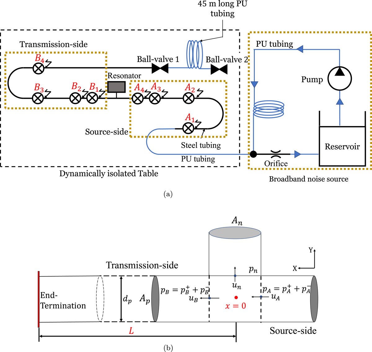
Schematic of the test-section and detailed view of the resonator neck. (a) Schematic of the experimental setup with source-side microphones (A1, A2, A3, A4) and transmission-side microphones (B1, B2, B3, B4). The entire flow system is the broadband noise source. There is no steady flow along the resonator in the main duct. (b) Schematic of the T-junction between the neck of the resonator and the main duct. The termination of the transmission side of the main pipe is either a closed end at the end of the steel tube (with closed ball-valve 1) or the PU tube termination (with closed ball-valve 2).
Current usage metrics show cumulative count of Article Views (full-text article views including HTML views, PDF and ePub downloads, according to the available data) and Abstracts Views on Vision4Press platform.
Data correspond to usage on the plateform after 2015. The current usage metrics is available 48-96 hours after online publication and is updated daily on week days.
Initial download of the metrics may take a while.