


| Issue |
Acta Acust.
Volume 10, 2026
|
|
|---|---|---|
| Article Number | 43 | |
| Number of page(s) | 11 | |
| Section | Acoustic Materials and Metamaterials | |
| DOI | https://doi.org/10.1051/aacus/2026023 | |
| Published online | 12 June 2026 | |
Scientific Article
Design and development of one-dimensional acoustic bundle ventilated metamaterial
1
Department of Design, Indian Institute of Technology Kanpur, Kalyanpur, Kanpur, Uttar Pradesh 208016, India
2
Microsystems Fabrication Laboratory, Department of Mechanical Engineering, Indian Institute of Technology Kanpur, Kalyanpur, Kanpur, Uttar Pradesh 208016, India
3
Boeing International Corporation India Private Limited, RMZ Infinity, Tower D, 5th Floor, Old Madras Road, Bengaluru 560001, Karnataka, India
* Corresponding author: This email address is being protected from spambots. You need JavaScript enabled to view it.
Received:
17
September
2025
Accepted:
9
March
2026
Abstract
The recent emergence of acoustic metamaterials presents unparalleled possibilities for sound control across diverse scenarios. However, achieving both sound absorption and unrestricted airflow concurrently in a one-dimensional scenario poses a challenge. Most available acoustic metamaterials are designed in 2D or 3D, and in these configurations, a large portion of noise is reflected back. The key challenge, therefore, is how to allow maximum air to pass through the structure, make it tunable and noise be effectively damped within it. To address this, we propose four different types of configurations as KF (Kink Fiber), YAM (“Y” Type kink Fiber), CDAM (Converging Diverging Kink Fiber), and IRAM (Internal Resonator Kink Fiber, a unique one-dimensional design that simultaneously overcomes both challenges. The design subwavelength (7 cm) one-dimensional acoustic meta-structured blanket, demonstrating broadband sound absorption bandwidth of one octave with 0.5–0.9 absorption within the 500–1600 Hz range. In this study, we theoretically (through transfer matrix method), numerically (through FEM), and experimentally (through Impedance tube method) have showcased that this challenge can be surmounted by employing various configurations of kink fiber-based metamaterials. Following the concept developed in this article there have been efforts to develop blankets using hand lay-up method which can be deployed in real-world setup based on one-dimensional acoustic damping concept introduced in this work.
Key words: Metamaterial / Noise shielding / Transfer matrix method / Kink fibers / Acoustic ventilation / One-dimensional
© The Author(s), Published by EDP Sciences, 2026
 This is an Open Access article distributed under the terms of the Creative Commons Attribution License (https://creativecommons.org/licenses/by/4.0), which permits unrestricted use, distribution, and reproduction in any medium, provided the original work is properly cited.
1 Introduction
Due to a rapid growth in the urban population, urban noise has become a significant environmental aspect that has a huge negative impact on individual’s health. This has led to the rise of the demand for more structures with internal air circulation capability serving the dual purpose of ventilation as well as noise dissipation in sectors like building spaces, transportation, halls and other suitable places etc. with moderated acoustics. A range of conventional sound-absorbing materials that are effective in reducing mid- and higher-frequency noise are frequently deployed to lessen its impact on human health, although a reduction of low/mid-frequency noise is a very challenging engineering aspect. Many ventilated metamaterials with significant noise attenuation levels have been proposed by researchers although the main drawback in a vast majority of the systems is that they reflect most of the incident sound waves. Achieving broadband sound absorption with one-dimensional ventilated metamaterial is quite an important and challenging area in acoustics which may serve many applications.
Acoustic metamaterials have advanced rapidly over the past 20 years in a variety of domains, including acoustic cloaking [1–4], subwavelength imaging [5, 6], topological acoustics [7, 8], and sound insulation and absorption [9–13], offering some of the unheard of means of controlling sound wave propagation which has both theoretical and practical values [14, 15]. The prior art has not involved the study related to free fluid flows through metamaterial structures [16, 17], instead, people have designed metamaterials with confined fluid flow. Another significant issue in acoustic engineering is absorption and insulation by ventilated meta-structures. This concept has numerous potential applications in real-world settings, including noise control for air conditioners, cars, and building ducts etc. Acoustic metamaterials [18–23], which are synthetic subwavelength unit structures have dynamical features not otherwise found in nature that have been used to design acoustic insulation ventilated channels (AIVC). Additionally, the vast majority of acoustic metamaterials with air circulation developed and demonstrated during the past few years have two-dimensional meta-surface geometries [24–30], and in some cases even three-dimensional geometry [31–33]. Most of the sound is reflected back by these metamaterials and not all sound passes through these which is also a fundamental flaw. Additionally, sound-insulating effectiveness and ventilation capacities have always had to be compromised when creating conventional acoustic barriers [34–36]. To address all these issues the current work reports one-dimensional ventilated acoustic metamaterial absorber (ODVAM). Moreover, the proposed design features a fully axial airflow path that enables nearly unobstructed ventilation. It also allows simpler tuning through a kinking (converging–diverging) structure and offers reduced fabrication complexity compared to 2D and 3D metasurfaces.
We present a ventilated metamaterial absorber (ODVMA) that can absorb incident energy with great efficiency (> 80%) in the range of 800–1200 Hz. The ODVMA, as its name suggests, does not require any reflectors, allowing fluids to flow in both directions. Additionally, the ODVMA can operate in both waveguides and free space, opening up a multitude of operational possibilities. We firstly propose a fabrication method to realize the ventilated panel and then numerically (FEM), theoretically and experimentally investigate the acoustic behavior and optimize the ventilation geometry of the proposed metamaterial. As depicted in Figure 1a, we show the fabrication method (Hand layup method) to realize the ODVAM panel. The glass hollow tube array is placed on the glass mat with interfacial adhesive in “x” direction as shown in Figure 1a where the interlayer gap is filled with the adhesive. This process is repeated in “y” direction with multiple layers of glass fiber mat and hollow fiberglass insulation sleeves to get the ventilated panel as shown in Figure 1b. The hollow glass fiber permits the flow of air passing through the absorber as well absorbs the sound by creating an acoustic impedance through the Helmholtz effect specially in kinked fibers as shown in Figure 1c.
 |
Figure 1. (a) Fabrication process and materials use for designing one-dimensional ventilated metamaterial. (b) Proposed acoustic ventilated panel. (c) The schematic diagram of the air ventilation and sound absorber of ODVAM. |
2 ODVAM design strategy
In this work, we have proposed five different kinds of hollow glass fiber tube unit cells to formulate the ODVAM panels and then characterized them thoroughly. The geometric parameters for the different configurations of the ventilated panels are illustrated in Table 1 below. The length of each tube is fixed at 7 cm. The first sample (A) is built entirely of glass mat, which restricts the panel’s ability to ventilate freely. This can be used as a baseline sample with no ventilation but a higher mass density. The sample (B) made of the hollow straight fibers allow to flow air freely although the density becomes a lot lesser due to the higher degree of hollowness. Sample (C), (D), (E) and (F) are fabricated with different kinking designs at the center of the hollow and allow free air to flow through. The kinking diameter of the unit cell (C), (D) and (E) is fixed at around 0.5 mm and for sample (F) is around 1 mm.
Geometric parameter of the all the unit cell of the proposed ODVAM.
We have carried out the acoustic impedance tube test on circular samples manufactured as per the impedance tube standards ASTM-E1050-12 [37]. The diameter of each sample is 100 mm and length is 7 cm. The different arrays of kinking hollow fibers are fabricated by using silicone coated fiberglass sleeves and the heat shrink tubes making up for the kinked shapes between two flanks of the one-dimensional hollow structures. The flank tubes are chosen diametrically up to different values based on the different geometries. The shrunk fits are made up of thermoplastic materials (Polyethylene terephthalate (PET)) and they shrink as they are exposed to heat. Shrinking temperature is approximately 70 ° C (158 °F) − 190 ° C (374 ° F) and density is approximately 1.38 g/cm3. The fabrication process of the sample is shown in Figure 2a. In order to experimentally verify the acoustic performance, the samples are fabricated as shown in Figure 2b. The outer cylindrical case is fabricated through 3D printing enabling the snug fitting of the outer layer of the hollow tube bundles. The material used is PLA and the printing of the bundle case is done with an accuracy of 0.1 mm.
 |
Figure 2. (a) The sample fabrication hand layup method, the dimension of the kink dia. approximately d 1 = 0.5 to 1 mm, L 1 and L 2 = 35 mm. (b) Created samples for acoustic impedance testing. |
3 Theoretical, experimental, and numerical modeling
It has been observed that the kink channels greatly improve the sound absorption performance of the structure, while retaining the open part to ensure the air ventilation performance of the structures. The resonance frequency of the channel’s length determines the first-order resonance frequency of the structure, and has the interrelationship [38], as shown in the equation (1). The measured frequency consistently tends to be lower than the theoretical calculation, suggesting that the pipe exhibits an acoustic length somewhat longer than its physical length. The extent of this lengthening is contingent on the pipe’s radius. To address this discrepancy, an additional corrective length is incorporated into the formulation and is called end correction factor [35], as shown in equation (2).
 (1)
(1)
 (2)
(2)
The equation (1) is valid for the unform cross section open tube geometries, where c 0 is the speed of sound in the air, L i is the effective length of the tube, L T is the total length of the tube, f i is the resonance frequency corresponding to the tube length and D is the diameter of the uniform pipe. At resonant frequencies, thermal viscous losses in the channels need to be considered. The channel’s attenuation coefficient “α” is provided by (3), [38]
 (3)
(3)
where “ω” is the angular frequency, “d” is the diameter of the hollow pipe, “μ” and “ρ0” are the viscosity coefficient and mass density of air, respectively. Resonance causes a significant increase in the thermal viscous loss of the acoustic wave energy inside the channels, and the coupling of these two processes viz., resonant behavior and the thermal and viscous losses, improve the structure’s capacity to insulate sound.
3.1 The transfer matrix method (TMM)
The transfer matrix method (TMM) shows the relationship between the initial sound pressure ‘p’ and the volume flux V. Assuming that the wave flowing inside the tube, as shown in Figure 3, is the plane wave and according to the continuity boundary conditions of sound pressure and velocity flux, we can get
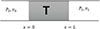 |
Figure 3. Schematic diagram of hollow glass fiber. |
![Mathematical equation: $$ \begin{aligned} {\left[ \begin{array}{c} p \\ v \end{array} \right]}_{x=0}=T{\left[ \begin{array}{c} p \\ v \end{array} \right]}_{x=L}=\left[ \begin{array}{cc} T_{11}&T_{12} \\ T_{21}&T_{22} \end{array} \right]\ {\left[ \begin{array}{c} p \\ v \end{array} \right]}_{x=L} \end{aligned} $$](/articles/aacus/full_html/2026/01/aacus250137/aacus250137-eq4.gif) (4)
(4)
where T is the system transfer matrix.
 (5)
(5)
 (6)
(6)
The absorption coefficient can be calculated as
 (7)
(7)
where  , Wave number.
The theoretical analysis of kinked hollow fibers is discussed in detail and calculation of the attenuation coefficient made in Supplementary material [Note S1] and the fundamental resonance frequency is ascertained. Over time, it has been noted that thermo-viscous boundary layer effects may have a major impact on the propagation of sound along small, channels having a rigid wall surface. This gives the contained air a substantial acoustic absorption effect in the audible frequency ranges.
Table 2 shows the physical properties of all the samples made into five differently arrayed unit cells. The weight of each sample, weight penalty imposed, the packing density and the corresponding frequency bandwidth which maximizes the sound absorption coefficient are shown in Table 2. The weight of all samples is kept nearly equal to that of the pure glass woven mat samples (GWM). The weight reduction of the sample as compared to GWM ranges from 3.9∼14.47%. The highest weight reduction is in the KFAM and the lowest is that in the IRAM. The open area for the ventilation is varied 49∼68% as compared to GWM, which is sufficient for the air circulation throughout the sample. The highest ventilation is in SFAM and lowest is in the IRAM. The sample volume of each sample is around 501 411.83 mm3. The benchmark sample in our case is the straight hollow fiber-based mat, which report a density of 678 kg/m3 and where the number of fibers is around 9000 and the total void volume is around 494 800.84 mm3.
Physical properties of the all the test sample made of the proposed ODVAM.
We first use ANSYS 2021 R1, Howard and Cazzolato [39] acoustic module to analyze the acoustic performance of the ODVAM. The setup details of the FEM simulations are shown in the supplementary section [Note S2]. To assess the acoustic performance of the meta-structures in the frequency domain (0–1600 Hz), a typical inbuilt pressure acoustic module is chosen. We take the single hollow fiber for the FEM simulation for study the acoustical properties of proposed different hollow fibers based one-dimensional ventilated metamaterial structures. The frictional resistance at the boundary between the air and the walls particularly on the kink walls causes most of the sound energy to dissipate. Figure 4(a–d) shows a matching experimental data in addition to the numerical simulation. According to ASTM E1050–12 standard, the acoustic absorption coefficient is measured in the tests using the standard B&K type-4206T impedance tube system is shown in the supplementary section [Note S3]. The experimentally measured absorption peak exhibits excellent agreement with the predictions of the simulations and theoretical proposed method. Simulation results show narrow and lower band as compared to experimental results because of the FEM simulation is performed generally in ideal condition. The differences occur due to attributed to the presence of the glass mat and the packing factor. In our case we took single fiber for do the FEM simulation and for the experiment, a circular sample (approx. 100 mm dia.) by using single fiber. To prepare the sample, we employed a glass mat on which a single kink fiber was positioned and rolled in a circular manner. Additionally, other factors like manufacturing limitations and the overall surface roughness of the hollow glass fibers and glass mats shows additional losses, resulting in the widening of the absorption spectrum.
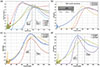 |
Figure 4. Sound absorption spectrum of experimental and numerical simulation of the four different sample with respect to frequency. (a) GWM, SHF and KF sample absorption spectrum. (b) YAM sound absorption spectrum signature. (c) CDAM metamaterials absorption spectrum signature. (d) IRAM metamaterials sound absorption spectrum signature. |
4 Results and discussion
Figure 4a shows the influence of kinking of hollow glass fiber on the acoustic performance of the metamaterials. Its shows that the absorption signature of the glass mat, hollow straight fiber and the kink fiber having the same length keep possessing a right shift in peak frequencies and that too for over different frequency ranges. The numerical simulation (Johnson–Champoux–Allard method) at the resonance frequency of glass mat exhibits a slightly higher value compared to the experimental results, attributed to the ideal conditions assumed in the FEM simulation. Notably, the simulation does not account for the effects of packing of the glass woven mat. The glass mat shows excellent relative sound absorption (higher than 50% over a wide frequency range) at frequencies 300–1600 Hz although it has a higher density and hinders the flow of air given the fully packed structure. Moreover, it also limits the application pertaining to air circulation which may be needed in a real-life scenario. For providing a defined path for air flow and getting maximum incident sound go through the structure which is otherwise not possible in 2D and 3D structures we have evaluated straight hollow fibers by kinking them at their center (lengthwise). The absorption signature of the hollow straight tube and kinked tube are shown in Figure 4a. The results show that the highest maximum sound absorption around 0.87, occurs at 1100 Hz in straight hollow fiber, but after incorporating a kink at the center, the absorption peak shifts towards the left and the new peak is achieved around 970 Hz. The % change of the shifting peak is calculated as 11.82%, [ ]. The absorption signature of another design within the shape of “Y” and the kink at the center is reported in the Figure 4b. There is no absorption peak shift as compared to the straight fiber as proposed in Table 1 in this geometry. The straight fiber has the diameter of 1 mm, and the “Y” type has the maximum diameter is 2 mm. But changing the larger diameter to 3 mm prompts the absorption peak to shift towards the left and it comes down by around 9%. The absorption signature (numerical and experimental) of CDAM design is reported in Table 1 [sample (E), shown in Fig. 4c]. The maximum sound absorption that is achieved at 900 Hz is 87%. The shifting of sound absorption peak is recorded to be around 18.18% and the sound absorption coefficient is higher than that of a straight hollow fiber. The last design is the IRAM as shown in Table 1, sample (f) and this is based on internal open resonator with a kinking point around the center (lengthwise). This geometry can be tuned as per the requirement in the range of 750–900 Hz without changing its height. The absorption spectrum of the IRAM sample is shown in Figure 4d. The sound absorption is higher than all the samples and it is more the 91%. The shifting of the resonance peak happens by 27%. as compared to straight hollow fibers. The detail physical configuration and dimensions of this geometry are illustrated in Figure 5.
 |
Figure 5. Geometric parameter and design of IRAM ventilated metamaterials. (a) isometric CAD view of IRAM and its dimensions, D1=D2=d. (b) The cad model and the fabricated unit sample. (c) Horizontally cut section of the IRAM unit cell. (d) Detailed view of IRAM. |
Figures 5a and 5c shows the schematic view of the unit IRAM cell, in which the internal resonators are clearly seen. The Figure 5b shows the cad model and the real unit cell of the IRAM sample. To demonstrate the notion, a thorough pilot simulation (FEM) using several geometrical parametric sweeps is carried out to establish the parametric range of each variable for the desired frequency range (0–1600 Hz). Figure 6a shows the corresponding sound absorption spectrum with internal pipe resonators ranging in length from 10∼60 mm while maintaining a fixed main kink at the end of the length 70 mm. As we increase the internal resonators length (l = l2 + lstraight + l2), the sound absorption peak begins to move to the left while also becoming lower in overall sound absorption efficiency (look at the lowering absorption coefficient), as seen in Figure 6a. Around 830 Hz, with l = 20 mm, the maximum amount of sound that is absorbed, shows a absorption coefficient of 90%. The sound absorption coefficient of the two extreme cases, one at l = 10 mm is around 87% at 850 Hz and second case when l = 60 mm, the absorption coefficient is around 82% at 750 Hz. As can be observed that as l2 is inversely proportional to the natural frequencies meaning thereby that as the length of the internal resonator increases the resonance frequency may shift to the left. Figure 6b shows the influence of the IRAM total resonators length (LT) on the overall sound absorption signature of the proposed structure. As the length of the kink resonators increase the absorption peak start shifting left. The resonance peak shifts by around 25%, when the length shifts from 70∼100 mm.
 |
Figure 6. (a) Sound absorption signature of the metastructure under different internal resonator length. (b) Sound absorption spectrum with varying total length of the IRAM fiber (LT). |
After a comprehensive comparison of all the proposed designs with the SHF configuration, each design was evaluated individually, and its advantages over SHF were systematically discussed. The tuning capability of the proposed designs was also analyzed in detail. Now, Figure 7 presents the experimental (impedance tube) sound absorption characteristics of SHM, KF, YAM, CDAM, and IRAM. Among these, IRAM demonstrates superior broadband sound absorption performance, achieving a sound absorption coefficient greater than 0.5 over the frequency range of 500 Hz to 1600 Hz, compared to the other proposed designs. It is further observed that introducing kinks in the hollow fiber shifts the sound absorption signature toward the lower frequency range while simultaneously enabling airflow through the structure. Specifically, the peak resonance of IRAM occurs at 800 Hz, whereas SHM exhibits its peak at 1100 Hz. This indicates that kinking the straight hollow fiber results in a left side shift of the acoustic absorption peak by more than 27%, without altering the fiber length.
 |
Figure 7. Impedance tube sound absorption signature of the proposed metamaterials SHM, KF, YAM, CDAM and IRM. |
5 Analysis of ventilation characteristics
GMM exhibits no ventilation, whereas SHF features 100% ventilation. The remaining four samples showcase almost complete airflow (nearly 100%) air flow through the structure with minimal reflection as shown in Table 3. In order to demonstrate the efficacy of the proposed models, it is crucial to not only assess their acoustic performance but also to incorporate CFD simulations. These simulations provide analyzing essential parameters such as pressure drop and velocity to further validate their effectiveness.
Ventilation characteristics of the all-unit cell of the proposed ODVAM.
To analyzing airflow performance of the ventilated one-dimensional structure, a Computational fluid dynamic (CFD), ANSYS workbench module was used. A pressure of 110 kPa (P atm = 101.32 kPa) pressure was used at one end of the fiber, while the opposite end was subjected to the gauge pressure 0 kPa pressure and then performed the FEM simulation. The pressure and velocity variation across the fiber as shown in Figures 8a and 8b. Based on the results, it becomes evident that as the velocity increases, there is a corresponding rise in pressure drop. Contour plots of ODAMs show in Figures 8c, how the air flow inside the fibers. All contour plots depict the inlet pressure of 110 kPa and corresponding velocities variations [40, 41]. The straight fiber and YAM fiber exhibited positive pressure drops, whereas the other fibers demonstrated negative pressure drops at the kinking point, resulting in enhanced absorption coefficient.
 |
Figure 8. (a) Air pressure signature across the fiber length. (b) Air velocity signature across the fiber length. (c) Contour plots of ODAM: pressure drop and velocity variation inside the fibers. |
6 Conclusions
In conclusion, we have numerically, theoretically, and experimentally verified a one-dimensional acoustic ventilated metastructure bundle that exhibits robust broadband sound absorption in the low- to mid-frequency range (500–1600 Hz). The sound absorption peak shift differs across different fiber types when compared to the straight hollow fiber. Specifically, the kinking fiber shows a 11.82% shift, Y type fiber exhibits a 9% shift, CDAM fiber experiences an 18.18% shift, and IRAM fiber demonstrates a 27% shift. According to the experimental findings, a higher relative bandwidth results in almost complete sound absorption. It has also been demonstrated that by altering the various geometrical parameters, the acoustical performance of the suggested metastructure design may be customized over a broad frequency range. Additionally, high absorptive behavior over broadband frequency range is accomplished by kinking the fiber and then shifting the kink lengthwise to arrive at several different scenarios. The configuration of coupling between the flants and shirring in the in between interconnect also leads to a broadband winde ranging behavior. The suggested concepts show their utility in engine shielding and architectural acoustics, both of which demand vented air flow with good noise-isolating capabilities. Finally, our suggested plan work well for low- to mid-range acoustic frequencies in small spaces that need adequate ventilation and very little sound refraction.
Acknowledgments
This work was supported by Boeing International Corporation India Private Limited (Grant No. BOEING/ME/2016081).
Data availability statement
The data that support the findings of this study are available from the corresponding author upon request.
Supplementary material
See the supplementary material for the details of the theoretical analysis (Note S1) and setup of numerical simulation (Note S2) and experimental setup (Note S3). Access Supplementary Material
References
- G.W. Milton, M. Briane, J.R. Willis: On cloaking for elasticity and physical equations with a transformation invariant form. New Journal of Physics 8, 10 (2006) 248–248. [Google Scholar]
- S.A. Cummer, D. Schurig: One path to acoustic cloaking. New Journal of Physics 9, 3 (2007) 45–45. [Google Scholar]
- H. Zhang, J. He, C. Liu, F. Ma: A wideband acoustic cloak based on radar cross section reduction and sound absorption. Applied Acoustics 213 (2023) 109639. [Google Scholar]
- C. House, J. Cheer, S. Daley: An experimental investigation into active structural acoustic cloaking of a flexible cylinder. Applied Acoustics 170 (2020) 107436. [CrossRef] [Google Scholar]
- V.M. García-Chocano, J. Christensen, J. Sánchez-Dehesa: Negative refraction and energy funneling by hyperbolic materials: an experimental demonstration in acoustics. Physical Review Letters 112 (2014) 11–15. [Google Scholar]
- J. Li, L. Fok, X. Yin, G. Bartal, X. Zhang: Experimental demonstration of an acoustic magnifying hyperlens. Nature Materials 8 (2009) 931–934. [Google Scholar]
- H. He, C. Qiu, L. Ye, X. Cai, X. Fan, M. Ke, F. Zhang, Z. Liu: Topological negative refraction of surface acoustic waves in a Weyl phononic crystal. Nature 560 (2018) 61–64. [Google Scholar]
- T. Liu, X. Zhu, F. Chen, S. Liang, J. Zhu: Unidirectional wave vector manipulation in two-dimensional space with an all passive acoustic parity-time-symmetric metamaterials crystal. Physical Review Letters 120 (2018) 124502. [Google Scholar]
- S. Kumar, P. Bhushan, O. Prakash, S. Bhattacharya: Double negative acoustic metastructure for attenuation of acoustic emissions. Applied Physics Letters 112 (2018) 101905. [Google Scholar]
- S. Bhattacharya, S. Kumar, S.K. Singh, P. Bhushan, M. Sahu, O. Prakash: Ashok chakra-structured meta-structure as a perfect sound absorber for broadband low-frequency sound. Applied Physics Letters 117 (2020) 191901 https://doi.org/10.1063/5.0022998. [Google Scholar]
- S.K. Singh, O. Prakash, S. Bhattacharya: Novel fractal acoustic metamaterials (FAMs) for multiple narrow-band near-perfect absorption. Journal of Applied Physics 132 (2022) 035105. [Google Scholar]
- N. Gao, J. Liu, J. Deng, D. Chen, Q. Huang, G. Pan: Design and performance of ultra-broadband composite meta-absorber in the 200 Hz-20 kHz range. Journal of Sound and Vibration 574 (2024) 118229. [Google Scholar]
- N. Gao, L. Tang, J. Deng, K. Lu, H. Hou, K. Chen: Design, fabrication and sound absorption test of composite porous metamaterial with embedding I-plates into porous polyurethane sponge. Applied Acoustics 175 (2021) 107845. [Google Scholar]
- G. Ma, P. Sheng: Acoustic metamaterials: from local resonances to broad horizons. Science Advances 2 (2016) e1501595. [Google Scholar]
- M. Yang, P. Sheng: Sound absorption structures: from porous media to acoustic metamaterials. Annual Review of Materials Research 47 (2017) 83–114. [Google Scholar]
- N. Gao, J. Wu, K. Lu, H. Zhong: Hybrid composite meta-porous structure for improving and broadening sound absorption. Mechanical Systems and Signal Processing 154 (2021) 107504. [CrossRef] [Google Scholar]
- N. Gao, B. Wang, K. Lu, H. Hou: Teaching-learning-based optimization of an ultra-broadband parallel sound absorber. Applied Acoustics 178 (2021) 107969. [CrossRef] [Google Scholar]
- H.L. Zhang, Y.F. Zhu, B. Liang, J. Yang, J. Yang, J.C. Cheng: Omnidirectional ventilated acoustic barrier. Applied Physics Letters 111 (2017) 203502. [Google Scholar]
- T. Lee, T. Nomura, E.M. Dede, H. Iizuka: Ultrasparse acoustic absorbers enabling fluid flow and visible-light controls. Physical Review Applied 11 (2019) 024022. [CrossRef] [Google Scholar]
- M. Sun, X. Fang, D. Mao, X. Wang, Y. Li: Broadband acoustic ventilation barriers. Physical Review Applied 13 (2020) 044028. [Google Scholar]
- L. Shen, Y. Zhu, F. Mao, S. Gao, Z. Su, Z. Luo, H. Zhang, B. Assouar: Broadband low-frequency acoustic metamuffler. Physical Review Applied 16 (2021) 064057. [Google Scholar]
- Z. Su, Y. Zhu, S. Gao, H. Luo, H. Zhang: High-efficient and broadband acoustic insulation in a ventilated channel with acoustic metamaterials. Frontiers in Mechanical Engineering 8 (2022) 857788. [Google Scholar]
- X. Xiang, H. Tian, Y. Huang, X. Wu, W. Wen: Manually tunable ventilated metamaterial absorbers. Applied Physics Letters 118 (2021) 053504. [CrossRef] [Google Scholar]
- S. Kumar, T.B. Xiang, H.P. Lee: Ventilated acoustic metamaterial window panels for simultaneous noise shielding and air circulation. Applied Acoustics 159 (2020) 107088. [Google Scholar]
- S. Kumar, H.P. Lee: Labyrinthine acoustic metastructures enabling broadband sound absorption and ventilation. Applied Physics Letters 116 (2020) 134103. [CrossRef] [Google Scholar]
- R. Dong, D. Mao, X. Wang, Y. Li: Ultrabroadband acoustic ventilation barriers via hybrid-functional metasurfaces. Physical Review Applied 15 (2021) 024044. [Google Scholar]
- S. Kumar, J.W. Aow, H.P. Lee: Acoustical performance of ventilated aluminum T-slot columns-based sonic cage. Applied Acoustics 193 (2022) 108779. [Google Scholar]
- Crivoi, L. Du, Z. Fan: Ventilated acoustic meta-barrier based on layered Helmholtz resonators. Applied Acoustics 205 (2023) 109263. [CrossRef] [Google Scholar]
- S.K. Singh, S. Bhattacharya: Recent progress in programmable acoustic metamaterials and their principles: a review. Journal of Micromanufacturing 2025 https://doi.org/10.1177/25165984251379272. [Google Scholar]
- M. Stanko, M. Golan: Hexagonal reciprocating pump: advantages and weaknesses. International Journal of Fluid Machinery and Systems 6 (2013) 121–136. [Google Scholar]
- G. Fusaro, X. Yu, Z. Lu, F. Cui, J. Kang: A metawindow with optimised acoustic and ventilation performance. Applied Sciences (Switzerland) 11, 7 (2021) 3168. [Google Scholar]
- J. Du, Y. Luo, X. Zhao, X. Sun, Y. Song, X. Hu: Bilayer ventilated labyrinthine metasurfaces with high sound absorption and tunable bandwidth. Scientific Reports 11 (2021) 5829. [Google Scholar]
- C. Gao, C. Hu, B. Hou, X. Zhang, S. Li, W. Wen: Ventilation duct silencer design for broad low-frequency sound absorption. Applied Acoustics 206 (2023) 109324. [CrossRef] [Google Scholar]
- J. Kang, M.W. Brocklesby: Feasibility of applying micro-perforated absorbers in acoustic window systems. Applied Acoustics 66 (2005) 669–689. [Google Scholar]
- X. Yu, S.K. Lau, L. Cheng, F. Cui: A numerical investigation on the sound insulation of ventilation windows. Applied Acoustics 117 (2017) 113–121. [Google Scholar]
- N. Yuya, N. Sohei, N. Tsuyoshi, Y. Takashi: Sound propagation in soundproofing casement windows. Applied Acoustics 70 (2009) 1160–1167. [Google Scholar]
- E.-A. Standard Test Method for Impedance and Absorption of Acoustical Materials Using a Tube, Two Microphones and a Digital Frequency Analysis System. ASTM E 1050-12 ASTM International 2012, I (2012) 4–9. [Google Scholar]
- L.E. Kinsler, A.R. Frey, A.B. Coppens J.V. Sanders: Fundamentals of Acoustics. John Wiley & Sons, 2010. [Google Scholar]
- C.Q. Howard, B.S. Cazzolato: Acoustic Analyses Using: MATLAB® and ANSYS®, 2014. DOI: https://doi.org/10.1201/b17825. [Google Scholar]
- R. Stobart, A. Wijewardane: Exhaust System Heat Exchanger Design for Thermal Energy Recovery in Passenger Vehicle Applications. Woodhead Publishing Limited, 2011. [Google Scholar]
- S. Baruah, S. Chatterjee: CFD analysis on an elliptical chamber muffler of a C.I. Engine. International Journal of Heat and Technology 37 (2019) 613–619. [Google Scholar]
Cite this article as: Singh S.K. Prakash O. & Bhattacharya S. 2026. Design and development of one-dimensional acoustic bundle ventilated metamaterial. Acta Acustica, 10, 43. https://doi.org/10.1051/aacus/2026023.
All Tables
All Figures
|
Figure 1. (a) Fabrication process and materials use for designing one-dimensional ventilated metamaterial. (b) Proposed acoustic ventilated panel. (c) The schematic diagram of the air ventilation and sound absorber of ODVAM. |
| In the text | |
|
Figure 2. (a) The sample fabrication hand layup method, the dimension of the kink dia. approximately d 1 = 0.5 to 1 mm, L 1 and L 2 = 35 mm. (b) Created samples for acoustic impedance testing. |
| In the text | |
|
Figure 3. Schematic diagram of hollow glass fiber. |
| In the text | |
|
Figure 4. Sound absorption spectrum of experimental and numerical simulation of the four different sample with respect to frequency. (a) GWM, SHF and KF sample absorption spectrum. (b) YAM sound absorption spectrum signature. (c) CDAM metamaterials absorption spectrum signature. (d) IRAM metamaterials sound absorption spectrum signature. |
| In the text | |
|
Figure 5. Geometric parameter and design of IRAM ventilated metamaterials. (a) isometric CAD view of IRAM and its dimensions, D1=D2=d. (b) The cad model and the fabricated unit sample. (c) Horizontally cut section of the IRAM unit cell. (d) Detailed view of IRAM. |
| In the text | |
|
Figure 6. (a) Sound absorption signature of the metastructure under different internal resonator length. (b) Sound absorption spectrum with varying total length of the IRAM fiber (LT). |
| In the text | |
|
Figure 7. Impedance tube sound absorption signature of the proposed metamaterials SHM, KF, YAM, CDAM and IRM. |
| In the text | |
|
Figure 8. (a) Air pressure signature across the fiber length. (b) Air velocity signature across the fiber length. (c) Contour plots of ODAM: pressure drop and velocity variation inside the fibers. |
| In the text | |
Current usage metrics show cumulative count of Article Views (full-text article views including HTML views, PDF and ePub downloads, according to the available data) and Abstracts Views on Vision4Press platform.
Data correspond to usage on the plateform after 2015. The current usage metrics is available 48-96 hours after online publication and is updated daily on week days.
Initial download of the metrics may take a while.