| Issue |
Acta Acust.
Volume 10, 2026
|
|
|---|---|---|
| Article Number | 24 | |
| Number of page(s) | 13 | |
| Section | Acoustic Materials and Metamaterials | |
| DOI | https://doi.org/10.1051/aacus/2026020 | |
| Published online | 06 April 2026 | |
Scientific Article
A gradient radial seismic metamaterial designed using the PSO algorithm
1
School of Civil and Environmental Engineering, The University of New South Wales, Sydney 2052, Australia
2
School of Civil Engineering and Architecture, Anyang Normal University, Anyang 455000, PR China
3
Henan Province Engineering Technology Research Center of Digital-Intelligent Building and Low-Carbon Building Materials, Anyang Normal University, Anyang 455000, Henan, PR China
* Corresponding author: This email address is being protected from spambots. You need JavaScript enabled to view it.
Received:
24
September
2025
Accepted:
19
February
2026
Abstract
This study proposes a gradient radial seismic metamaterial that integrates typical engineering core geometries with particle swarm optimization (PSO) algorithm and placement optimization to realize low-frequency, broadband surface-wave attenuation in compact footprints. Under an equal-area constraint and a band-diagram objective focused on the first two bands, the T-shaped unit emerges as the most effective core, and a front-rear graded assembly superposes Bragg-scale gaps to span 5–35 Hz, aligning with the dominant frequencies of destructive surface waves. Cylindrical-coordinate finite-element dispersion analysis, 3D frequency-domain response spectra, and time-domain excitation with the 1984 Bishop record collectively verify marked reductions in stress, displacement, and peak acceleration within the target frequency, confirming engineering feasibility. The approach addresses scalability and material-use constraints while lowering onset frequency and widening the primary band gap, offering a practical pathway for building-level seismic shielding.
Key words: Seismic metamaterial / Radial gradient design / Structural optimization / Frequency-time domain validation
© The Author(s), Published by EDP Sciences, 2026
 This is an Open Access article distributed under the terms of the Creative Commons Attribution License (https://creativecommons.org/licenses/by/4.0), which permits unrestricted use, distribution, and reproduction in any medium, provided the original work is properly cited.
1 Introduction
Earthquakes, as a sudden and catastrophic natural hazard, not only pose a severe threat to human life and safety but also result in substantial property losses, exerting profound negative impacts on economic development and social progress, and significantly hindering the overall advancement of human society [1–3]. In traditional seismic design, structures primarily depend on passive energy dissipation, achieved either through inherent mechanical properties or by incorporating damping and isolation devices to reduce seismic energy [4, 5]. However, conventional approaches often exhibit limited robustness and provide only marginal efficacy for controlling and suppressing ultra-low-frequency vibrations [6], while also struggling to accommodate the complex construction and operational conditions commonly encountered in engineering practice. Consequently, overcoming these limitations has emerged as a central focus of recent research and development efforts.
Metamaterials [7] constitute engineered composites whose unusual physical responses arise primarily from deliberately architected microstructures rather than their base chemistry. By finely tuning unit-cell geometry and periodic arrangement, these materials afford precise control over wave propagation, with pronounced benefits for the creation and tuning of band gaps [8–10]. Such capabilities translate into strong prospects for applications in vibration mitigation and acoustic-wave manipulation [11, 12].
Seismic metamaterials, grounded in the metamaterial paradigm, are a class of engineered functional materials that modulate elastic-wave propagation through artificially periodic architectures, with the central objective of creating band gaps aligned with the typical 0–20 Hz frequency range of seismic surface waves to achieve shielding and attenuation [13]. Two principal physical underpinnings are involved: modal coupling induced by local resonance [14] and periodic destructive interference arising from Bragg scattering [15, 16], both serving to block or diminish energy transmission. Recent studies have sought to overcome the design bottleneck of achieving low-frequency broadband band gaps by leveraging strategies such as inertial amplification, negative-stiffness effects, and multi-material hybridization, thereby realizing pronounced subwavelength low-frequency attenuation and isolation within finite structural footprints.
Driven by the pronounced increase in displacement and the attendant risks of overturning and pounding that conventional isolation systems exhibit under near-fault, long-period ground motions, researchers turned at the end of the last century to a seismic metamaterial pathway centered on the band gap mechanism, aiming to actively manipulate and reduce surface elastic-wave energy at the wave scale and thereby transcend the limitations of relying solely on compliant isolation layers. Early material- and wave-level evidence based on phononic crystal band gap theory emerged first, with Meseguer and colleagues [17] in 1999 drilling periodic circular-hole arrays in marble and observing pronounced scattering and attenuation of surface elastic waves, thereby establishing the physical basis for suppressing Rayleigh waves with two-dimensional elastic band gap structures and furnishing key proof for importing band gap concepts into earthquake engineering. Over the ensuing decade and more, the field progressed from concept validation to full-scale testing in engineering sites, with Brûlé and co-workers [18] in 2014 installing a periodic array of vertical empty inclusions in natural soil and using a monochromatic vibrocompaction source in a field trial, which demonstrated that such periodic structuring can reshape the surface wave field and produce marked attenuation and deflection effects for Rayleigh waves around 50 Hz, thus signaling a shift of seismic metamaterials from theory and small-scale experiments toward empirical validation in engineering contexts. In this temporal sequence, the excessive displacement and control limitations faced by conventional isolation in long-period scenarios served as a major driver for this research pivot, while the wave-suppression mechanism of band gap periodic structures, together with field-feasibility evidence, laid the groundwork for further engineering exploration of seismic metamaterials.
Last decade, to overcome the bottleneck of low-frequency broadband band gap design, research has advanced along two complementary paths, namely mechanism innovation and structural optimization, thereby fostering the coordinated development of seismic metamaterials. Miniaci et al. [19] proposed a large-scale mechanical metamaterial barrier and investigated the feasibility of achieving a locally resonant band gap of 6.72–20 Hz using steel-rubber resonators, but noted that the band gap width remained limited and difficult to extend. Subsequently, Colquitt et al. [20] identified forests as natural seismic metamaterials and elucidated how local resonances of trees can induce Rayleigh-wave band gaps below 150 Hz, thereby inspiring bioinspired design strategies. Liu et al. [21] introduced the concept of negative stiffness and studied metamaterial units incorporating negative-stiffness dynamic absorbers, demonstrating that tuning to a critical negative-stiffness ratio yields quasi-static band gaps with near-zero onset frequency, thus overcoming the traditional mass constraint. Li et al. [22] proposed a hinged inertial amplification architecture and examined how geometric amplification of effective inertia can widen the band gap to 0–13 Hz, with scaled experiments confirming attenuation exceeding 30 dB. Thereafter, Lim and Żur [23] designed a steel surface barrier and assessed its engineering applicability for realizing a low-frequency band gap of 6.72–20 Hz in layered soils. Furthermore, Chen et al. [24] introduced gradient V/N-shaped metamaterials and analyzed how concrete-based unit combinations broaden the band gap to 1.06–10.90 Hz.
Driven by prior studies, the use of seismic metamaterials for building protection has made substantial progress. Nevertheless, a number of urgent challenges remain. On one hand, many schemes rely on large-scale periodic structures, which can introduce stability concerns and, due to heavy material demand and high costs, hinder practical deployment. On the other hand, miniaturized units often shift the operating band toward higher frequencies after downscaling, providing insufficient suppression of more destructive low-frequency surface waves. In addition, commonly adopted designs typically feature narrow band gaps, constraining the effective attenuation bandwidth for seismic waves. Moreover, barrier layouts are relatively uniform, limiting adaptability to the complex and variable spectra of seismic waves.
This study addresses the aforementioned challenges by introducing typical engineering geometric elements into a radial seismic metamaterial framework, proposing multiple configurations and performing band gap optimization under an equal-area constraint to systematically assess and enhance low-frequency vibration mitigation capacity and band gap breadth. By jointly comparing band gap width and the lowest onset frequency, candidate configurations with superior seismic performance are identified to ensure more stable attenuation across seismically relevant low-frequency bands. Building on this, PSO is integrated with a graded design philosophy to develop a gradient radial seismic metamaterial that achieves a broad band gap within 5–35 Hz while improving material utilization, thereby strengthening control over and dissipation of seismic surface waves. To verify the engineering applicability and functional feasibility of the proposed structure, frequency-domain response analysis and time-domain impact simulations are conducted to cross-validate amplitude suppression and propagation attenuation within the band gap-related frequency range.
2 Methods
2.1 Radial metamaterial elastic wave equation
An applied localized force in an elastic medium induces relative displacements among neighboring particles, which, through the medium’s elasticity, couple the disturbed point to its surroundings and generate additional restoring forces. These restoring forces set adjacent particles successively into motion, whereby the disturbance is transmitted incrementally and expands outward as a propagating perturbation that develops via interparticle interactions, namely elastic forces, this propagating perturbation is termed an elastic wave [25]. Under the standard assumptions of elastodynamics, one may consider an arbitrarily small volume element in an isotropic medium and formulate the fundamental governing equations that relate particle force to displacement and stress to strain, which serve to describe the generation and propagation of elastic waves.
The differential equation of motion:
 (1)
(1)
The geometric equation:
 (2)
(2)
The physical equation:
 (3)
(3)
ρ denotes the density of the medium, F i denotes the external body force per unit mass, and λ and μ denote the elastic constants of the medium for elastic waves.
Using the displacement u as the unknown, and based on the three fundamental relations given in equations (1)–(3), the wave equation governing elastic-wave propagation in the medium can be derived:
![Mathematical equation: $$ \begin{aligned} \rho \ddot{{u}}=\sum \limits _{j=1}^3 {\left\{ {\frac{\partial }{\partial x_{i} }\left( {\lambda \frac{\partial u_{j} }{\partial x_{j} }} \right)+\frac{\partial }{\partial x_{j} }\left[ {\mu \left(\frac{\partial u_{i} }{\partial x_{j} }+\frac{\partial u_{j} }{\partial x_{i} }\right)}\right]}\right\} } +\rho F_{i}. \end{aligned} $$](/articles/aacus/full_html/2026/01/aacus250154/aacus250154-eq4.gif) (4)
(4)
Equation (4) presents the wave equation for elastic waves in an inhomogeneous and anisotropic elastic medium, in which both the density and the elastic constants vary with the spatial coordinates (x, y, z), and in the absence of body forces the equation can be written in vector form.
![Mathematical equation: $$ \begin{aligned} \rho (\boldsymbol{r})\ddot{{\boldsymbol{u}}}=\nabla \left[ {\left( {\lambda (\boldsymbol{r})+2\mu (\boldsymbol{r})} \right)\nabla \cdot \boldsymbol{u}} \right]-\nabla \times \left( {\mu (\boldsymbol{r})\nabla \times \boldsymbol{u}} \right). \end{aligned} $$](/articles/aacus/full_html/2026/01/aacus250154/aacus250154-eq5.gif) (5)
(5)
For a metamaterial configuration formed by the composite of dissimilar constituents, the elastic waves within it are governed by the wave equations given in equations (4) and (5). When the lattice exhibits periodicity only along two mutually orthogonal directions, i.e., for a two-dimensional metamaterial, the plane spanned by the two periodic directions is conventionally taken as the xOy plane, with the axis normal to this plane defined as the Z axis. Because the medium is treated as homogeneous along the z direction, considering wave propagation confined to the xOy plane implies that the displacement depends on x and y but not on z, whereby the governing equations for in-plane and out-of-plane motions decouple, referred to as the X Y mode and the Z mode, respectively. The vector form of the X Y mode equation then follows to characterize the evolution of the in-plane displacement field.
![Mathematical equation: $$ \begin{aligned} \begin{aligned} \rho (\boldsymbol{r})\frac{\partial ^{2}u_{x} }{\partial t^{2}}&=\frac{\partial }{\partial x}\left[ {\lambda (\boldsymbol{r})\left( {\frac{\partial u_{x} }{\partial x}+\frac{\partial u_{y} }{\partial y}} \right)} \right]\\&\quad +\frac{\partial }{\partial x}\left[ {2\mu (\boldsymbol{r})\frac{\partial u_{x} }{\partial x}} \right]+\frac{\partial }{\partial y}\left[ {\mu (\boldsymbol{r})\left( {\frac{\partial u_{x} }{\partial y}+\frac{\partial u_{y} }{\partial x}} \right)} \right], \\ \rho (\boldsymbol{r})\frac{\partial ^{2}u_{y} }{\partial t^{2}}&=\frac{\partial }{\partial y}\left[ {\lambda (\boldsymbol{r})\left( {\frac{\partial u_{x} }{\partial x}+\frac{\partial u_{y} }{\partial y}} \right)} \right]\\&\quad +\frac{\partial }{\partial x}\left[ {\mu (\boldsymbol{r})\left( {\frac{\partial u_{x} }{\partial x}+\frac{\partial u_{y} }{\partial y}} \right)} \right]+\frac{\partial }{\partial y}\left[ {2\mu (\boldsymbol{r})\frac{\partial u_{y} }{\partial y}} \right]. \end{aligned} \end{aligned} $$](/articles/aacus/full_html/2026/01/aacus250154/aacus250154-eq6.gif) (6)
(6)
The scalar equation for the Z mode is:
![Mathematical equation: $$ \begin{aligned} \rho (\boldsymbol{r})\frac{\partial ^{2}u_{z} }{\partial t^{2}}=\frac{\partial }{\partial x}\left[ {\mu (\boldsymbol{r})\frac{\partial u_{z} }{\partial x}} \right]+\frac{\partial }{\partial y}\left[ {\mu (\boldsymbol{r})\left( {\frac{\partial u_{z} }{\partial y}} \right)} \right]. \end{aligned} $$](/articles/aacus/full_html/2026/01/aacus250154/aacus250154-eq7.gif) (7)
(7)
In view of the structure’s radial characteristics, a finite element method formulated in cylindrical coordinates is adopted to analyze the metamaterial’s radial band gap behavior. First, the governing equations of elastic waves are established in cylindrical coordinates to compute the dispersion curves of an infinite periodic system. In this notation, u, v, and w denote the displacement components along r, θ, and z, ρ denotes the density, t denotes time, λ and μ are the Lamé constants, and r, θ, z are the three coordinates of the cylindrical system.
 (8)
(8)
The definitions of the volumetric strain θ t and the rotation components w′r, w′θ, and w′z are as follows:
 (9)
(9)
The elastodynamic equations in cylindrical coordinates include terms that depend on θ, which generally couple the radial displacement u, the circumferential displacement v, and the axial displacement w. In this study, the radial metamaterial is analysed under an axisymmetric loading assumption, where the external excitation is applied only in the r–z plane and the circumferential traction is taken to be zero. Accordingly, the circumferential displacement and the corresponding θ-direction stress and strain components can be set to zero, and the field variables become independent of θ. With this simplification, the original three-dimensional problem is therefore reduced to an equivalent two-dimensional axisymmetric formulation in the r–z plane. In the subsequent dispersion analysis, a one-dimensional Bloch wave vector k r is introduced only along the radial periodic direction. As a result, along the Γ–X path in the radial direction, only the axisymmetric in-plane branch originates from the Γ point, whereas the additional in-plane mixed branch that could emerge in a full two-dimensional non-axisymmetric model is excluded under the present assumption. In addition, because the Bloch–Floquet condition is applied only along the radial periodic direction and the lattice constant a is fixed, the computed band structure is expected to be dominated by the unit-cell topology and its geometric/placement parameters, with only a minor dependence on the absolute radial reference location of the representative unit cell in the r–z plane [26, 27].
2.2 PSO algorithm
Compared with traditional optimization methods, PSO leverages swarm-coordinated global exploration combined with memory of individual and swarm historical bests, effectively reducing the probability of getting trapped in local optima in high-dimensional multimodal search spaces and accelerating convergence toward a near-global optimum [28]. Its modeling and implementation are simple, with few hyperparameters and strong interpretability, low costs for engineering deployment and reproducibility, and native suitability for parallel computing to increase evaluation throughput and time efficiency. By configuring and scheduling the inertia weight and acceleration coefficients, a controllable trade-off between exploration and exploitation can be achieved, and adaptive weighting and parameter strategies can be incorporated to enhance stable convergence and robustness. Compared with swarm intelligence methods such as genetic algorithms, PSO requires neither crossover nor mutation, uses fewer parameters and a simpler implementation, typically converges faster, and is easier to couple with local search, surrogate modeling, multiobjective schemes, and constraint-handling frameworks to form an efficient hybrid optimization pipeline that further improves solution quality and engineering applicability. Therefore, PSO combines efficiency and ease of use in scalability, robustness, and global search capability, reflects comprehensive advantages over traditional algorithms, and is suitable for a wide range of engineering optimization and data-driven modeling tasks.
To obtain the optimal solution, each particle is attracted toward its previously attained personal best position (P best) and the swarm’s global best position (g best) [29]. In the context of minimizing the objective, it holds that
 (10)
(10)
With index  , and
, and
 (11)
(11)
In this formulation, i indexes the particles with  , t denotes the current iteration, f is the objective function to be minimized, x represents the position vector as a candidate solution, and N is the swarm size, and the velocity and position of particle i are updated at iteration t + 1 as follows:
 (12)
(12)
 (13)
(13)
Here, v denotes the velocity vector, ω is the inertia weight that balances local exploitation and global exploration, r1 and r2 are random vectors uniformly sampled from [0, 1]D (with D the search-space dimensionality), and c1 and c2, referred to as acceleration coefficients, are positive constants. The specific optimization process of the PSO algorithm is shown in Figure 1.
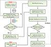 |
Figure 1. The PSO algorithm flowchart. |
3 The selection and optimization of 2D unit cells
3.1 Comparison of radial seismic metamaterials employing square unit cells of differing geometries
This section, based on a radial seismic metamaterial unit cell arranged on a square lattice, specifies a core cross-sectional area of 0.552 π m2 and constructs four regular-geometry cores together with four engineering-standard cores (channel-, I-, T-, and L-shaped), as illustrated in Figure 2. Throughout the study, the lattice constant a is fixed at 2 m. In the figures, yellow denotes soil and gray denotes steel, and the corresponding material parameters are provided in Table 1.
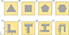 |
Figure 2. Schematic of a 2D radial seismic metamaterial featuring four types of regular polygonal cores and four typical engineering core geometries: (a) equilateral triangle-shaped, (b) square-shaped, (c) regular pentagon-shaped, (d) regular hexagon-shaped, (e) L-shaped, (f) T-shaped, (g) I-shaped, (h) channel-shaped. |
Material parameters of the unit cell.
The overall numerical simulations were performed in COMSOL Multiphysics using an axisymmetric model built with the Solid Mechanics module. Periodic boundary conditions were applied on the left and right boundaries to represent an infinitely periodic structure [19, 30], whereas free boundary conditions were imposed on the top and bottom boundaries to reflect the mechanical response in the absence of external constraints.
Figure 3 presents the band structures along the Γ-X direction for radial seismic metamaterials with square unit cells featuring four types of regular polygonal cores, and shows the mode shapes at the highest frequency of the first band and the lowest frequency of the second band. Figure 3a depicts a radial seismic metamaterial with a square unit cell and an equilateral triangular core with a side length of 1.48 m, exhibiting a complete band gap between the first and second bands spanning 10.808–29.530 Hz. Figure 3b shows the counterpart with a square core of side length 0.97 m, for which the complete band gap from the first to the second band covers 9.367–28.386 Hz. Figures 3c and 3d correspond to square unit cells with regular pentagonal and regular hexagonal cores, with side lengths of 0.74 m and 0.61 m, respectively. The corresponding complete band gaps extend over 9.464–28.121 Hz and 9.358–27.707 Hz, respectively.
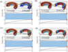 |
Figure 3. Band structures and mode shape results for radial seismic metamaterial designs featuring four types of regular polygonal cores: (a) equilateral triangle-shaped, (b) square-shaped, (c) regular pentagon-shaped, (d) regular hexagon-shaped. |
Analysis of the mode shapes at both edges of the complete band gap indicates that at the lower edge corresponding to the highest frequency of the first band, all types of regular polygonal cores undergo an approximately rigid-body translation together with the unit cell as a whole. At the upper edge corresponding to the lowest frequency of the second band, the displacement in each square unit-cell configuration is concentrated in the unit-cell soil matrix, while the core displacement is approximately zero.
Figure 4 illustrates the band structures of square radial seismic metamaterial unit cells with four shapes commonly used in engineering, together with the displacement mode shapes at the lower and upper bounds of their complete band gaps. Figure 4a shows a square radial seismic metamaterial unit cell with an L-shaped steel core, with geometric parameters d = 0.5 m, h = 1 m, l = 0.9 m, θ = 0°, and a complete band gap between the first and second bands from 9.5–23.30 Hz. Figure 4b shows the counterpart with a T-shaped steel core, with geometric parameters d = 0.5 m, h = 1 m, l = 0.9 m, θ = 0°, and a complete band gap between the first and second bands from 9.77–26.19 Hz. Figure 4c shows the unit cell with an I-shaped steel core, with geometric parameters d = 0.5 m, h = 0.6 m, l = 0.65 m, θ = 0°, and a complete band gap between the first and second bands from 8.93–24.64 Hz. Figure 4d shows the unit cell with a frame-shaped steel core, with geometric parameters d = 0.5 m, h = 0.6 m, l = 0.65 m, θ = 0°, and a complete band gap between the first and second bands from 9.40–28.62 Hz. The displacement-mode pattern at the bounds of the band gaps for these four engineering-shaped cores is consistent with that of the regular-polygon cores in Figure 3, namely, at the highest frequency of the first band the cores undergo an approximately rigid-body translation with the unit cell as a whole, whereas at the lowest frequency of the second band the displacement is mainly concentrated in the unit-cell soil domain and the core displacement is nearly zero.
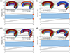 |
Figure 4. Band structures and mode shape results for radial seismic metamaterial designs featuring four widely used engineering core shapes: (a) L-shaped, (b) T-shaped, (c) I-shaped, (d) channel-shaped. |
A comprehensive analysis of eight square radial seismic metamaterial unit cells with different core shapes shows that, in all cases, a clear and relatively wide complete band gap appears between the first and second bands. Compared with unit cells employing regular polygonal cores, those with engineering-common core shapes are more amenable to parameter optimization. In view of the significant influence of spatial arrangement and core geometry on the band gap width, the engineering-common core shapes core unit cell is selected for subsequent parameter optimization to identify the optimal shape and spatial layout.
3.2 Structural parameter optimization based on the PSO algorithm
Based on the Bragg scattering mechanism, the spatial arrangement and geometric parameters of the unit cell play a decisive role in band gap formation in radial seismic metamaterials, and therefore this section conducts parameter optimization for square radial seismic metamaterial unit cells with engineering-common core shapes using the PSO algorithm. Under the constraint of a constant steel cross-sectional area, the geometric parameters d, h, l, and θ are systematically optimized across different configurations to investigate the effects of structural scale and placement on band gap formation and widening. Based on the band structure analyses in the previous section, the complete band gap is most likely to occur between the first and second bands, and thus the optimization objective is to maximize the complete band gap width, i.e., maximize ΔΨ = Ψmin, 2 − Ψmax, 1. The optimization workflow is implemented in a coupled COMSOL Multiphysics and MATLAB environment, with automated modeling, solving, and data extraction enabled via LiveLink for MATLAB.
This study formulates the inverse dessign of square radial seismic metamaterials unit cell as an optimization problem.
 (14)
(14)
 (15)
(15)
Equation (14) defines Ψ as the desired band gap width dependent on d, h, l, and θ, min F r e i + 1 refers to the lower bound of band i + 1, while max F r e i indicates the upper bound of band i.
As shown in Figure 5a, under the condition of the widest band gap, the band structure of the L-shaped radial seismic metamaterial unit cell corresponds to geometric parameters d = 0.63846 m, h = 0.9 m, l = 0.58848 m, and θ = 325.14°, with a band gap frequency range of 10.061–26.568 Hz and a total width of 16.507 Hz. Figure 5b shows the band structure of the T-shaped core radial seismic metamaterial unit cell under the widest band gap condition, with geometric parameters d = 0.4 m, h = 0.94171 m, l = 1.4341 m, and θ = 270.01°, yielding a band gap frequency range of 10.923–34.681 Hz and a total width of 23.758 Hz. Figure 5c presents the band structure of the I-shaped core radial seismic metamaterial unit cell after parameter optimization, with geometric parameters d = 0.40603 m, h = 0.6164 m, l = 0.86207 m, and θ = 310.97°, showing a band gap frequency range of 11.534–30.948 Hz and a width of 19.414 Hz. Figure 5d provides the band structure of the frame-shaped radial seismic metamaterial unit cell, with geometric parameters d = 0.4 m, h = 0.52433 m, l = 1.3272 m, and θ = 220.21°, with a band gap frequency range of 11.274–31.225 Hz and a width of 19.951 Hz.
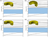 |
Figure 5. Band structure results for radial seismic metamaterials with four representative engineering core profiles, at the conditions yielding the narrowest and the widest gaps: (a) L-shaped, (b) T-shaped, (c) I-shaped, (d) channel-shaped. |
A comparative analysis of the parameter optimization results for the aforementioned engineering-shaped cores shows that, as presented in Table 2, the radial seismic metamaterial unit cell with a T-shaped core exhibits the widest bandgap distribution and thus demonstrates stronger vibration-isolation potential.
Comparative table of band gap characteristics before and after optimization for radial seismic metamaterials with four commonly used engineering core shapes.
4 Gradient design of T-shaped core radial seismic metamaterial unit cell
4.1 Response spectrum validation of the gradient design for the fundamental unit cell and the expanded unit cell
Although Section 3 conducted computational analyses of the band structures for different core shapes and proposed parameter optimization schemes for unit cells with engineering-common core geometries, further independent verification is required to ensure the reliability of the results. In this section, a three-dimensional model of the T-shaped core radial seismic metamaterial unit cell is constructed and arranged periodically within the soil domain, and its response spectrum is computed for comparative validation, as shown in Figure 6. The structure consists of eight T-shaped-core unit cells arranged periodically in a radial ring configuration. Figure 6a presents a top view and schematic of the periodic arrangement under the 3D modeling setup; the red circle indicates the seismic-wave excitation location, the red dashed circle indicates the receiving/monitoring location, and PML layers are applied around the model to reduce the influence of boundary reflections on the computation [31, 32]. Figure 6b shows the corresponding response spectrum, in which two pronounced peaks appear in the frequency ranges 10–30 Hz and 40–50 Hz. This spectral feature is consistent with the band structure of the T-shaped optimal configuration shown in Figure 5b, thereby validating the accuracy and reproducibility of the preceding computational results.
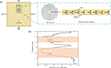 |
Figure 6. (a) Schematic of a periodically arranged, T-shaped-core radial seismic metamaterial, (b) Response spectrum of the T-shaped-core radial seismic metamaterial after parameter optimization. |
Despite achieving a relatively wide band gap through parameter optimization, the operational frequency band of the structure still lies mainly above 10 Hz, and given that surface waves in seismic motions are highly destructive with dominant frequencies typically in the 0–10 Hz range, it remains necessary to further lower the band gap lower bound of the designed structure to meet engineering needs. Based on the Bragg scattering mechanism, the characteristic scale of a metamaterial is approximately inversely related to the frequency range of its band gap, so enlarging the structural dimensions can shift the band gap toward lower frequencies. This section introduces a gradient design concept to develop a new composite radial seismic metamaterial structure that achieves a wide band gap in the low-frequency range to enhance seismic adaptability. Building upon the existing square radial seismic metamaterial unit cell with a T-shaped core, all geometric dimensions of the unit cell are doubled relative to their original values, and a three-dimensional schematic model is established as shown in Figure 7a. The gradient scheme adopts a front–rear arrangement, in which three rows of upscaled unit cells are embedded along the outer side of the overall structure, while a 3 × 2 matrix of baseline unit cells is placed in the interior. To reduce the computational cost, the present model does not employ the PML absorbing layers used in Figure 6a at the outer boundary indicated by the black frame; instead, low-reflection boundary conditions are applied to effectively suppress the influence of soil-boundary reflections on the computed results. Its low-frequency broadband vibration-attenuation performance is evaluated by computing the response spectrum and modal characteristics.
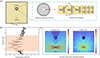 |
Figure 7. (a) Schematic of a radial seismic metamaterial with a T-shaped core in a front-and-rear gradient arrangement, (b) Response spectrum of the T-shaped gradient radial seismic metamaterial, (c) Three-dimensional von Mises stress distributions at 5 Hz and 30 Hz. |
From Figure 7b, a pronounced peak appears in the response spectrum within the 5–35 Hz band, which is consistent with the frequency-domain prediction of Bragg scattering theory. Figure 7c shows the von Mises stress distributions of the designed T-shaped gradient radial seismic metamaterial under 5 Hz and 30 Hz excitations, where the structure exhibits effective seismic-wave shielding at both frequencies. Notably, at 30 Hz, the seismic wave field is relatively dispersed, likely due to its shorter wavelength, yet the designed structure still exhibits a clearly observable and effective seismic-wave shielding effect. Taken together, these observations indicate that the proposed gradient design effectively achieves the superposition of band gaps across multiple frequency bands, thereby expanding the usable band gap range and enhancing vibration-isolation performance.
4.2 Verification in the frequency domain for the 3D structure derived from the optimal gradient design
In the previous section, a gradient square radial seismic metamaterial based on a T-shaped core was proposed and validated, with an effective operating frequency band of approximately 5–35 Hz. On this basis, this section models the structure in three dimensions and embeds it in a soil domain, evaluates its seismic performance under different input frequencies by frequency-domain simulations, and sets the embedment depth to H = 2a. Figure 8a provides a schematic of the overall three-dimensional structure in the x-z plane, where red arrows indicate the locations of seismic excitation and signal reception. Figure 8b presents a comparison of von Mises stress with and without the designed structure over the 0–50 Hz band, showing that introducing the T-shaped gradient radial seismic metamaterial markedly reduces stress in the target region and demonstrates effective seismic mitigation. Figure 8c shows the displacement mode of the soil-metamaterial system at 5 Hz, indicating that seismic waves are effectively blocked. Figure 8d provides the displacement comparison results, where isolated abnormal peaks at very low frequencies may result from numerical error at extremely low frequency, while the other frequencies consistently demonstrate the feasibility of the designed structure and its stable vibration-reduction performance.
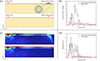 |
Figure 8. Variation of von Mises stress and displacement amplitude with and without the embedded gradient T-shaped radial seismic metamaterial (a) Schematic of the model in the x-z plane, (b) von Mises stress comparison, (c) Displacement mode-shape comparison at 5 Hz, (d) Displacement comparison. |
4.3 Dynamic performance analysis and characterization of the radial seismic metamaterial under seismic loading
Given that real earthquake waves are elastic waves whose frequencies vary periodically with time, evaluating the seismic isolation and vibration reduction performance of radial seismic metamaterials based on a single frequency or a narrow frequency band cannot comprehensively characterize their dynamic behavior. Accordingly, this section selects the 1984 Bishop earthquake wave (Shows in Fig. 9a) to conduct time-domain simulations under recorded ground motion on the designed radial seismic metamaterial structure, in order to further verify its seismic performance under real earthquake excitations. The three-dimensional time-domain finite element model is consistent with the setup in Figure 8a, and both the seismic-wave excitation location and the signal-receiving location are identical. The time-domain analysis spans 0–50 s with 1000 sampled time points, thereby ensuring the accuracy and numerical stability of the computed results.
Figure 9b compares the acceleration time histories with and without embedding the gradient radial seismic metamaterial, where the peak acceleration of the soil is markedly attenuated after the structure is incorporated, with the amplitude reduced to approximately one-half of the original.
Figure 9c compares the displacement time histories, demonstrating effective suppression of displacement in the target area despite a low-frequency drift common to both cases, which is characteristic of the input motion. The observed drift phenomenon in the displacement time-history curves of Figure 9c, characterized by a persistent increase over time, is a quasi-static response primarily attributable to the abundant long-period components inherent in the 1984 Bishop earthquake record (Fig. 9a), whose influence is amplified through the double integration process from acceleration to displacement. This low-frequency drift is further influenced by the numerical model’s absorbing boundary conditions, which, while highly effective for wave absorption within the target 5–35 Hz band, are less perfect for motions approaching 0 Hz, permitting a slow rigid-body displacement of the soil mass. Crucially, the concurrent manifestation of this drift in both configurations (with and without the metamaterial) confirms that it stems from the input motion and model characteristics, not a deficiency in the metamaterial’s design. The core function of the graded radial seismic metamaterial is the attenuation of dynamic wave energy within its operational band, a purpose it fulfills effectively, as evidenced by the marked reduction in displacement amplitude within the shielded region throughout most of the event, thereby robustly validating its efficacy in suppressing dynamic wave propagation and verifying its engineering feasibility.
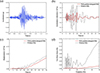 |
Figure 9. Acceleration and displacement response comparison under real seismic waves, contrasting configurations with versus without radial seismic metamaterials (a) Time-domain plot of the Bishop wave, (b) Comparison of acceleration with and without radial seismic metamaterials under the influence of the Bishop wave, (c) Comparison of displacement with and without radial seismic metamaterials under the influence of the Bishop wave, (d) Comparison of von Mises stress with and without radial seismic metamaterials under the influence of the Bishop wave. |
Figure 9d displays the von Mises stress-time history, indicating that within the target frequency band, especially in the low-frequency range, embedding the radial seismic metamaterial significantly reduces the soil stress level in the target region.
In summary, validated by time-domain excitation using real earthquake records, the designed T-shaped gradient radial seismic metamaterial provides notable seismic benefits for buildings by effectively reducing peak acceleration and stress in the low-frequency range.
5 Conclusion
In this study, an engineering-oriented, gradient-designed radial seismic metamaterial is proposed and implemented by coupling typical engineering cross-sectional geometries with PSO and placement optimization. Under an equal-area constraint and an objective focused on the first two bands, an optimal configuration centered on a T-shaped unit is obtained, and a front-rear graded assembly achieves superposition of Bragg-scale band gaps so that the primary gap spans approximately 5–35 Hz, aligning with the dominant frequency band of destructive surface waves. Using cylindrical-coordinate finite-element dispersion analysis, three-dimensional frequency-domain response, and time-domain excitation with a real earthquake record (the Bishop wave), a three-fold validation shows marked reductions in stress, displacement, and peak acceleration within the target band, confirming the feasibility and stable vibration-mitigation performance of the proposed structure in engineering scenarios.
The study achieves concurrent advances in lowering the band-gap onset frequency, widening the primary band gap, and improving material utilization and scalability, thereby offering a compact-footprint, material-efficient, and readily implementable pathway for building-scale seismic shielding.
Funding
The authors acknowledge the support from Key Scientific and Technological Projects of Henan Province of China (252102320026), Higher Education Key Scientific Research Project of Henan Province of China (25B130001), Higher Education Teaching Reform Research and Practice Project of Henan Province of China (2024SJGLX0157).
Conflicts of interest
The authors declare that they have no known competing financial interests or personal relationships that could have appeared to influence the work reported in this paper.
Data availability statement
Data are available on request from the authors.
References
- S. Han, B. Liu, J. Yang, T. Feng, J. Luo, Z. Zhou, H. Gong: Impact assessment of the effects of strong earthquake-induced hazards on the socioeconomic development level of earthquake-stricken areas after the 2008 Wenchuan earthquake. Mobile Information Systems 2022 (2022) 1695637. [Google Scholar]
- J. Zhao, X. Li, S. Chen, C. Liu: Multi-source driven estimation of earthquake economic losses: a comprehensive and interpretable ensemble machine learning model. International Journal of Disaster Risk Reduction 106 (2024) 104377. [Google Scholar]
- Y. Li, D. Xin, Z. Zhang: Estimating the economic loss caused by earthquake in Mainland China. International Journal of Disaster Risk Reduction 95 (2023) 103708. [Google Scholar]
- L.Y. Lu, T.K. Lin, S.W. Yeh: Experiment and analysis of a leverage-type stiffness-controllable isolation system for seismic engineering. Earthquake Engineering & Structural Dynamics 39 (2010) 1711–1736. [Google Scholar]
- H.H. Tsang, S. Lo, X. Xu, M. Neaz Sheikh: Seismic isolation for low-to-medium-rise buildings using granulated rubber–soil mixtures: numerical study. Earthquake Engineering & Structural Dynamics 41 (2012) 2009–2024. [Google Scholar]
- P. Li, F. Yang, P. Wang, J. Zhao, Z. Zhong: A novel design scheme for acoustic cloaking of complex shape based on region partitioning and multi-origin coordinate transformation. Applied Mathematics and Mechanics 43 (2022) 1641–1656. [Google Scholar]
- C. Jiang, H. Nie, M. Chen, X. Shen, L. Xu: Achieving environmentally-adaptive and multifunctional hydrodynamic metamaterials through active control. Advanced Materials 37 (2025) 2313986. [Google Scholar]
- S. Yang, Y. Liu, T. Liang: Band structures in the nematic elastomers phononic crystals. Physica B: Condensed Matter 506 (2017) 55–64. [CrossRef] [Google Scholar]
- S. Yang, X. Zhou, Y.-F. Wang: Tunable band gap and wave guiding in periodic grid structures with thermal sensitive materials. Composite Structures 290 (2022) 115536. [CrossRef] [Google Scholar]
- S. Yang, J.-H. Yin, X.-J. Zhu, K. Wang, S.-k. Zhang, L. Cao, P.-Y. Guo, Y. Liu: Investigation and optimal design of band gap tunability in fractal phononic crystals. Acta Acustica 9 (2025) 18. [Google Scholar]
- X.-L. Zhou, J.-H. Yin, K. Wang, S. Yang, L. Cao, P.-Y. Guo: Band gap tuning and wave separator design in 3D composite slab structures based on periodic thermal fields. Mechanics of Advanced Materials Structures 32 (2025) 1343–1351. [Google Scholar]
- K. Wang, J.-H. Yin, L. Cao, P.-Y. Guo, G.-T. Fan, J.-Y. Qin, S. Yang: Investigation on waveguide and directional transmission properties of a tunable liquid–solid phononic crystal based on rotation of scatterer. Nano 20 (2025) 2450132. [CrossRef] [Google Scholar]
- C. Zhao, Q. Chen, Y. Wang: Low-frequency band gap seismic metamaterials for Lamb wave based on vibration-sensitive scatterers. Journal of Vibration Engineering & Technologies 12 (2024) 7903–7915. [Google Scholar]
- C. Cai, S. Deng, Q. Xiong, D. Wu, C. Li: Tuning fork seismic metamaterial for low-frequency surface wave attenuation with locally resonant band gaps. Journal of Vibration Engineering & Technologies 12 (2024) 4039–4051. [Google Scholar]
- K. Zhang, J. Luo, F. Hong, Z. Deng: Seismic metamaterials with cross-like and square steel sections for low-frequency wide band gaps. Engineering Structures 232 (2021) 111870. [Google Scholar]
- L. Gao, C. Cai, C.M. Mak, X. He, Y. Zou, D. Wu: Surface wave attenuation by periodic hollow steel trenches with Bragg band gap and local resonance band gap. Construction and Building Material 356 (2022) 129289. [Google Scholar]
- F. Meseguer, M. Holgado, D. Caballero, N. Benaches, J. Sanchez-Dehesa, C. López, J. Llinares: Rayleigh-wave attenuation by a semi-infinite two-dimensional elastic-band-gap crystal. Physical Review B 59 (1999) 12169. [Google Scholar]
- S. Brûlé, E. Javelaud, S. Enoch, S. Guenneau: Experiments on seismic metamaterials: molding surface waves. Physical Review Letters 112 (2014) 133901. [Google Scholar]
- M. Miniaci, A. Krushynska, F. Bosia, N.M. Pugno: Large scale mechanical metamaterials as seismic shields. New Journal of Physics 18 (2016) 083041. [CrossRef] [Google Scholar]
- D. Colquitt, A. Colombi, R. Craster, P. Roux, S. Guenneau: Seismic metasurfaces: sub-wavelength resonators and Rayleigh wave interaction. Journal of the Mechanics and Physics of Solids 99 (2017) 379–393. [Google Scholar]
- Y. Liu, S. Lin, Y. Li, C. Li, Y. Liang: Numerical investigation of Rayleigh waves in layered composite piezoelectric structures using the SIGA-PML approach. Composites Part B: Engineering 158 (2019) 230–238. [Google Scholar]
- L. Li, Q. Wang, H. Liu, L. Li, Q. Yang, C. Zhu: Seismic metamaterials based on coupling mechanism of inertial amplification and local resonance. Physica Scripta 98 (2023) 045024. [Google Scholar]
- C. Lim, K.K. Żur: Wide Rayleigh waves bandgap engineered metabarriers for ground born vibration attenuation. Engineering Structures 246 (2021) 113019. [Google Scholar]
- C. Chen, J. Lei, Z. Liu: A ternary seismic metamaterial for low frequency vibration attenuation. Materials 15 (2022) 1246. [Google Scholar]
- Q. Yang, K. Su, L. Li, Y. Li, J. Bai: Radial gradient seismic metamaterials with ultra-low frequency and ultra-wide band gap. Applied Sciences 13 (2023) 9284. [Google Scholar]
- D. Torrent, J. Sánchez-Dehesa: Radial wave crystals: radially periodic structures from anisotropic metamaterials for engineering acoustic or electromagnetic waves. Physical Review Letters 103 (2009) 064301. [Google Scholar]
- I. Arretche, K.H. Matlack: Effective phononic crystals for non-Cartesian elastic wave propagation. Physical Review B 102 (2020) 134308. [Google Scholar]
- A.G. Gad: Particle swarm optimization algorithm and its applications: a systematic review. Archives of Computational Methods in Engineering 29 (2022) 2531–2561. [Google Scholar]
- Y. Zhang, S. Balochian, P. Agarwal, V. Bhatnagar, O.J. Housheya: Artificial intelligence and its applications 2014. Mathematical Problems in Engineering 2016 (2016). [Google Scholar]
- L. Li, Q. Jia, M. Tong, P. Li, X. Zhang: Radial seismic metamaterials with ultra-low frequency broadband characteristics. Journal of Physics D: Applied Physics 54 (2021) 505104. [Google Scholar]
- U. Basu, A.K. Chopra: Perfectly matched layers for time-harmonic elastodynamics of unbounded domains: theory and finite-element implementation. Computer Methods in Applied Mechanics and Engineering 192 (2003) 1337–1375. [Google Scholar]
- R. Clayton, B. Engquist: Absorbing boundary conditions for acoustic and elastic wave equations. Bulletin of the Seismological Society of America 67 (1977) 1529–1540. [Google Scholar]
Cite this article as: Gu J.-F. Yin J.-H. Li X.-D. Jiang L. Zhang S.-K. & Yang S. 2026. A gradient radial seismic metamaterial designed using the PSO algorithm. Acta Acustica, 10, 24. https://doi.org/10.1051/aacus/2026020.
All Tables
Comparative table of band gap characteristics before and after optimization for radial seismic metamaterials with four commonly used engineering core shapes.
All Figures
|
Figure 1. The PSO algorithm flowchart. |
| In the text | |
|
Figure 2. Schematic of a 2D radial seismic metamaterial featuring four types of regular polygonal cores and four typical engineering core geometries: (a) equilateral triangle-shaped, (b) square-shaped, (c) regular pentagon-shaped, (d) regular hexagon-shaped, (e) L-shaped, (f) T-shaped, (g) I-shaped, (h) channel-shaped. |
| In the text | |
|
Figure 3. Band structures and mode shape results for radial seismic metamaterial designs featuring four types of regular polygonal cores: (a) equilateral triangle-shaped, (b) square-shaped, (c) regular pentagon-shaped, (d) regular hexagon-shaped. |
| In the text | |
|
Figure 4. Band structures and mode shape results for radial seismic metamaterial designs featuring four widely used engineering core shapes: (a) L-shaped, (b) T-shaped, (c) I-shaped, (d) channel-shaped. |
| In the text | |
|
Figure 5. Band structure results for radial seismic metamaterials with four representative engineering core profiles, at the conditions yielding the narrowest and the widest gaps: (a) L-shaped, (b) T-shaped, (c) I-shaped, (d) channel-shaped. |
| In the text | |
|
Figure 6. (a) Schematic of a periodically arranged, T-shaped-core radial seismic metamaterial, (b) Response spectrum of the T-shaped-core radial seismic metamaterial after parameter optimization. |
| In the text | |
|
Figure 7. (a) Schematic of a radial seismic metamaterial with a T-shaped core in a front-and-rear gradient arrangement, (b) Response spectrum of the T-shaped gradient radial seismic metamaterial, (c) Three-dimensional von Mises stress distributions at 5 Hz and 30 Hz. |
| In the text | |
|
Figure 8. Variation of von Mises stress and displacement amplitude with and without the embedded gradient T-shaped radial seismic metamaterial (a) Schematic of the model in the x-z plane, (b) von Mises stress comparison, (c) Displacement mode-shape comparison at 5 Hz, (d) Displacement comparison. |
| In the text | |
|
Figure 9. Acceleration and displacement response comparison under real seismic waves, contrasting configurations with versus without radial seismic metamaterials (a) Time-domain plot of the Bishop wave, (b) Comparison of acceleration with and without radial seismic metamaterials under the influence of the Bishop wave, (c) Comparison of displacement with and without radial seismic metamaterials under the influence of the Bishop wave, (d) Comparison of von Mises stress with and without radial seismic metamaterials under the influence of the Bishop wave. |
| In the text | |
Current usage metrics show cumulative count of Article Views (full-text article views including HTML views, PDF and ePub downloads, according to the available data) and Abstracts Views on Vision4Press platform.
Data correspond to usage on the plateform after 2015. The current usage metrics is available 48-96 hours after online publication and is updated daily on week days.
Initial download of the metrics may take a while.