| Issue |
Acta Acust.
Volume 10, 2026
Topical Issue - Modern approaches to Active Control of Sound and Vibration
|
|
|---|---|---|
| Article Number | 34 | |
| Number of page(s) | 8 | |
| Section | Topical Issue - Modern approaches to Active Control of Sound and Vibration | |
| DOI | https://doi.org/10.1051/aacus/2026037 | |
| Published online | 12 May 2026 | |
Scientific Article
Noise mitigation with active acoustic metamaterials
1
Department of Mechanical Engineering, University of Michigan, Ann Arbor, Michigan 48109, USA
2
Department of Electrical Engineering and Computer Science, University of Michigan, Ann Arbor, Michigan 48109, USA
3
Toyota Research Institute of North America, Ann Arbor, Michigan 48105, USA
* Corresponding author: This email address is being protected from spambots. You need JavaScript enabled to view it.
Received:
31
December
2025
Accepted:
7
April
2026
Abstract
The potential of active metamaterials to address long-standing challenges such as noise mitigation has been recognized for several decades. However, the research of active structures capable to meet these challenges has been slow due to issues such as stability and limited bandwidth. This work will feature a class of active metamaterials composed of independent unit cells with sensors and actuators connected through electronics that impose desired transfer functions between these elements. We experimentally demonstrate two implementations of these active metamaterials for the application of noise mitigation. In the first case, a two-dimensional metamaterial is digitally programmed to behave with complex effective bulk modulus and mass density that have matched phases. With these properties, the metamaterial achieves very high sound absorption, but is well-matched to the background and thus scatters very little. Moreover, its acoustic behavior can be switched from opaque absorber to transparent medium on very small time scales. In the second case, broadband noise absorption in a duct is targeted through the design of a one-dimensional active metamaterial with analog circuitry. The transmission loss can be increased by adding cells to the metamaterial while maintaining stable performance.
Key words: Acoustics / Metamaterials / Active metamaterials / Noise / Active noise control
© The Author(s), Published by EDP Sciences, 2026
 This is an Open Access article distributed under the terms of the Creative Commons Attribution License (https://creativecommons.org/licenses/by/4.0), which permits unrestricted use, distribution, and reproduction in any medium, provided the original work is properly cited.
1 Introduction
Noise has long been correlated with an increased incidence in cardiovascular diseases [1], making noise mitigation an important area of research. Numerous passive absorbers have been developed but they tend to be either ineffective, too bulky, narrow band, or scatter sound instead of dissipating it [2, 3]. It has been proposed that metamaterials with their extra degrees of freedom to manipulate sound can advance this strategically important field. Passive metamaterials have been tried first, but they suffered from the same limitations as conventional passive methods [4–7]. It was soon realized that active metamaterials can overcome these limitations [8–10]. A particularly promising active metamaterial architecture consists of sensor-driver pairs operating with an open loop proportional control strategy, where the effective acoustic properties are dictated by the chosen transfer function (or gain) between each pair of sensor and driver [11]. These gains are typically set in electronic circuits programmable in real time [12–17]. Importantly, in this active metamaterial design, the effective properties depend on the gains themselves, derived from a polarized source model [18], and not the adjustment of the sensed field to match a target state, as in feedback control [19, 20]. The advantages of this approach over a conventional controls strategy [3] are its scalability promoted by the independence of the sensor-driver pairs (i.e., there is no connection between different pairs) and very low response time stemming from the gains being computed apriori for a desired functionality and not adaptively. It has recently been shown that active metamaterials composed of sensor-driver pairs can achieve very high sound absorption with minimal scattering [17]. The effect has been studied in the steady state regime in which the effective properties of the metamaterial are fixed, but it is unknown whether switching these properties on-demand can be done in a stable manner. Additionally, though broadband operation is possible in principle, a drawback of the open loop control strategy is the dependence on the intrinsic transfer functions of the components, which must be accounted for so that the desired behavior occurs across frequencies. Most studies of this active metamaterial design to date have focused on performance at a single frequency or in a narrow band.
Here, we show experimentally with a two-dimensional (2D) active acoustic metamaterial the ability to rapidly switch from an opaque reflectionless absorber with complex bulk modulus and mass density to a transparent medium on-demand without adverse effects. We then investigate the potential for broadband performance with this active metamaterial design strategy in a configuration of reduced complexity, targeting the application of noise mitigation in a one-dimensional (1D) duct. In this case, the desired behavior is simply an out of phase response to the incident wave rather than certain effective acoustic properties, but the same proportional control is employed so that the findings are transferable to the more complex design. We consider the component frequency responses in detail and show how the modular nature of metamaterials can be leveraged to increase the transmission loss.
2 On-demand reflectionless absorber
The goal of this section is to realize a time-modulated 2D active acoustic absorbing medium that does not scatter impinging sound. The medium is represented by the red box in the air-filled acoustic waveguide of two parallel plates shown in Figure 1a. An incident wave is driven in the fundamental mode by an external speaker placed on the side of the waveguide. The air has bulk modulus B0, mass density ρ0, speed of sound c0 and characteristic impedance Z0.
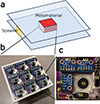 |
Figure 1. (a) Schematic of the experimental setup showing a medium of effective bulk modulus B and mass density ρ placed in a 2D waveguide and ensonified by an external speaker. (b) Programmable metamaterial realization of an effective medium with on-demand macroscopic effective B and ρ. (c) Photo of unit cell with the labeled microphones Mi and speakers Si, where |

Driven versus sensed quantities.
The medium is a very good absorber matched with the background as long as its bulk modulus B and mass density ρ are complex quantities given by
 (1)
(1)
where ϕ is a real phase. Under these conditions, the characteristic impedance of the medium matches that of air ( ) and the speed of sound
  is complex. High absorption is achieved when the imaginary part of c is large.
This continuous medium is realized with an active metamaterial composed of the 3 by 3 arrangement of active cells, each 4.6 cm in dimension, illustrated in Figure 1b. The metamaterial is under a good approximation flat, protruding very little in the waveguide and thus does not impede the flow of air. Consequently, in its off state, the metamaterial effective properties are those of air.
It has been shown that active cells composed of multiple sensor-driver pairs can fully program the effective bulk modulus, mass density tensor and two Willis coupling vectors depending on the configuration of the sensor and driver in each pair [10, 17]. The bulk modulus is controlled by a monopole sensor capturing the local pressure p and driving a monopole driver which has amplitude proportional to p. Each component α of the mass density tensor (α ∈ {x, y} in 2D) is controlled by a dipole sensor capturing the local particle velocity u α and driving a particle velocity source with amplitude proportional to u α .
Figure 1c shows a 2D metamaterial cell with three sensor-driver pairs to control the bulk modulus and all components of the mass density tensor. In this approach, the pressure and particle velocity components are obtained with three microphones Mi sensing the acoustic pressures pMi and driving the three speakers Si, where  . Speaker S1 is flush to the waveguide surface acting as a monopole pressure source, and speakers S2 and S3 are vertical, acting as dipole sources in the x and y directions respectively. The acoustic pressure p at the cell location is the average pressure sensed by all three microphones and the particle velocities are derived from pairs of microphones, with u
x
from M1 and M2, and u
y
from M1 and M3. The sensed quantities as well as the amplitude of the sound generated by these speakers A
Si
are shown in Table 1. The proportionality terms g
m
,
. Speaker S1 is flush to the waveguide surface acting as a monopole pressure source, and speakers S2 and S3 are vertical, acting as dipole sources in the x and y directions respectively. The acoustic pressure p at the cell location is the average pressure sensed by all three microphones and the particle velocities are derived from pairs of microphones, with u
x
from M1 and M2, and u
y
from M1 and M3. The sensed quantities as well as the amplitude of the sound generated by these speakers A
Si
are shown in Table 1. The proportionality terms g
m
,  ,
,  ,
,  , and
, and  are set by a Teensy 4 microcontroller connecting the microphones and speakers of each cell.
Closed-form expressions relating these gain terms to the desired effective material properties B and ρ given by equation (1) are derived elsewhere [17, 18]. To summarize, the acoustic behavior of continuous materials can be replicated by arrays of monopole and dipole sources with amplitudes that are proportional to the local acoustic field. The ideal gain magnitudes (proportionality constants) increase for acoustic properties further from those of the background material and for higher incident wave frequencies due to the size of the unit cell being larger relative to the wavelength. The prescribed phase of the response is independent of frequency, but depends on the phase of the acoustic properties. In the realization here, the programmable component of the gain is a constant scaling value and a fixed number of digital samples delay. In combination with the intrinsic frequency responses of the components and a three stage bandpass filter to ensure stability, the ideal magnitude and phase response is achieved exactly at one frequency. In its active state, the metamaterial is programmed to have B and ρ given by equation (1) with ϕ = 30° at f 0 = 1200 Hz. This phase produces a very large absorption. The microcontroller in each cell can reduce the gains g shown in Table 1 to zero essentially instantaneously (at the digital sampling rate of 96 kHz), switching the metamaterial to behave with acoustic transparency since its passive structure has negligible scattering.
The metamaterial is ensonified by a speaker at f 0 = 1200 Hz (the unit cells are smaller than a sixth of the wavelength at this frequency). We programmed the metamaterial to switch from the opaque, high absorption state (ϕ = 30°) to the transparent or off state (ϕ = 0°) every 1.67 ms, i.e., two acoustic periods at 1200 Hz. Figure 2 shows the time domain acoustic pressure fields measured inside and outside the metamaterial at two time instances separated by 1.67 ms with and without the metamaterial inside the waveguide.
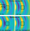 |
Figure 2. Time domain acoustic pressure measured in the empty waveguide (top) and with the time-modulated programmable metamaterial (bottom). The right pressure fields (transparent state) were measured 1.67 ms later than the left fields (absorber state), i.e., half the modulation period. |
The external speaker excites cylindrical waves in the empty waveguide (Fig. 2, top). The two time instances illustrated in the figure are chosen approximately two acoustic periods apart and thus the two measured acoustic pressure distributions are essentially the same.
The bottom panels represent the acoustic fields measured in the waveguide with the metamaterial inside. The black squares in the figure represent the position of the metamaterial. The same two instances separated by two acoustic periods shows the metamaterial behavior ϕ = 30° (absorber state) and ϕ = 0° (transparent state), respectively.
In the absorber state the metamaterial dissipates almost all of the incident energy as reflected by the very low amplitude pressure inside the structure and behind it (the shadow region). In all other directions, the acoustic pressure looks essentially the same as that measured in the empty waveguide at the same time instant, which confirms the expected negligible scattering behavior of the metamaterial. In its transparent state, the metamaterial behaves essentially as air, i.e., the measured fields look like those measured in the empty waveguide, confirming that the effective B and ρ match those of air.
The absorption of the active metamaterial is difficult to quantify directly from the behavior of the 3 × 3 arrangement of unit cells due to the edge effects. However, the transmission loss for the infinitely extending metamaterial with 1D propagation can be found analytically and is representative of the energy removed from the system since the metamaterial is reflectionless. The transmission loss is defined as
 (2)
(2)
where P i and P t are the incident and transmitted wave amplitudes respectively. A scattering matrix approach could be used to calculate the transmission loss from the source amplitudes, but since the metamaterial is characterized by the effective properties of Z = Z 0 and c = c 0 e j60°, it is simpler to solve for the scattering from a slab of continuous material. Assuming continuity of pressure and particle velocity at the interfaces, the ratio of the transmitted pressure to the incident pressure for a slab with complex acoustic properties is
 (3)
(3)
where k = 2π f 0/c and L is the width of the slab. Then, with equation (2), the theoretical transmission loss for a slab with the width of one active unit cell is 7.6 dB. Because the unit cell layers are reflectionless, the transmission loss scales linearly, yielding a transmission loss of 22.8 dB for three layers. At frequencies away from f 0, the loss would decrease and eventually transition to gain, potentially resulting in instability for a metamaterial consisting of a large number of cells.
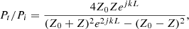
The metamaterial behavior for different time modulations is shown in Figure 3 as time domain acoustic pressures measured at a point in the transmitted region. The incident pulse is the same in all cases, rising to a steady-state of many periods before tapering off. With the metamaterial continuously on (see Fig. 3a), the active or scattered response is an out of phase and slightly reduced magnitude replication of the incident pulse. The total pressure is the sum of the incident and actively generated waves, which mostly cancel. A delay and slightly larger amplitude can be seen in the first few periods of the active response, which are due to the transient filter and speaker dynamics. The results are also shown for the metamaterial with an on/off cycle of 150 Hz and 300 Hz (see Figs. 3b & 3c respectively). The active and total pulse trains exemplify the ability to rapidly switch between noise absorption and transparency.
 |
Figure 3. Time domain acoustic pressures (incident, active response, and total) measured at a point in the transmitted region beyond the metamaterial for different on/off modulation frequencies: (a) continuously on, (b) f 0/8 = 150 Hz, and (c) f 0/4 = 300 Hz. |
3 Broadband absorber in a duct
The 2D absorber demonstrates the potential of the active metamaterials approach. However, most practical noise mitigation applications require broadband performance, which remains challenging to achieve. To investigate the influence of the component transfer functions and number of cells on the performance of locally controlled active metamaterials, the unit-cell design was simplified to a 1D configuration consisting of a pressure sensor and monopole driver. The microcontroller used in the previous design was replaced with analog circuitry to implement the filtering and proportional response, thereby eliminating latency associated with analog-to-digital and digital-to-analog conversion.
Within the effective-medium framework introduced for the 2D metamaterial, this design enables control only over the effective bulk modulus. Here, however, the objective is limited to the simplified task of generating an out-of-phase acoustic response rather than prescribing specific effective material parameters. Because the same proportional control strategy is employed, the insights obtained can be transferred to the more complex reflectionless absorber, which is a more powerful demonstration of the advantages of the active metamaterials approach.
The 1D metamaterial embedded in the walls of a duct is shown in Figure 4a. The motivating practical application is the reduction in low frequency noise without the use of material that would impede air flow. This can be achieved with ring-shaped passive resonators [21–23], but active solutions offer more flexibility and the potential to mitigate noise at lower frequencies without excessive bulk. The problem is well studied in the field of conventional active noise control [24, 25], where adaptive closed loop feedback, typically with a far upstream feedforward microphone, downstream error microphone, and secondary source, is used to cancel noise [9]. While the control strategy of updating the transfer functions for changing conditions can result in improved bandwidth, there is the drawback of a lengthy response time before the optimal performance is reached. Such systems can also be used to enhance transmission loss in passive metamaterials [26, 27], but these designs still entail obstruction of the airflow and the active component does not scale well. Multiple microphones and secondary sources may be used, but when employing centralized and nonlocal control, the design complexity rapidly increases with the number of components. In contrast, the simplicity of the local proportional control approach of our interest enables modeling many pairs with metamaterials methods. The performance can then be improved by increasing the number of unit cells such that the low amplitude individual responses sum to large collective noise reduction without instability.
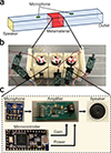 |
Figure 4. (a) Schematic of the duct with a noise source at one end and the active metamaterial integrated into the walls in the midsection. An upstream and downstream microphone are used to determine transfer functions and the transmission loss. (b) The sensing and driving elements of the metamaterial are mounted in modular unit cells. (c) The active components of the unit cell. |
The duct in the experimental setup is 2 m long and 5 cm wide, permitting a maximum frequency of 3400 Hz in the fundamental mode. The length enables time windowing to avoid reflections from the waveguide ends. A speaker is positioned at one end to drive the incident wave and microphones are positioned a short distance upstream and downstream from the metamaterial to measure the background (incident wave with the metamaterial off) and total fields (incident wave and the metamaterial response). The signals from these microphones are not incorporated in the processing of the active metamaterial but are only used to assess its performance. The metamaterial is pictured in Figure 4b. The active elements are individually epoxied to 3D printed cells that magnetically mount to a supporting 3D printed structure. The interior is maintained flush to the surrounding waveguide. The active elements can be easily interchanged or replaced with passive cells.
The electronic components of an active unit cell are shown in Figure 4c. The local acoustic pressure is measured by a single microphone and the response driven by a single speaker. The microcontroller is no longer used to process the acoustic signals. Instead, it sets the gain of an analog amplifier designed for this task. The amplifier consists of a low pass and a high pass filter stage, with stage gains adjustable via I2C programmable potentiometer and rheostat. Importantly, the total programmable gain, which is the product of the two stage gains, is set at a fixed value prior to operation rather than being adaptively updated. Additionally, it is simply a scalar, with any frequency dependent behavior being the result of the filter and speaker frequency responses.
For lossy behavior, the response phase may span from roughly 90° to 270° relative to the incident wave, with the exact band depending on the magnitude of the cell response relative to the incident wave magnitude. Outside of this band, the incident wave will be amplified instead of attenuated. An example theoretical transmission loss for an active metamaterial with this design strategy as a function of the number of cells and their response phase is shown in Figure 5. The transmission losses shown in Figure 5 were calculated through a transfer matrix model of the active metamaterial, using example cell response magnitude one third that of the incident, frequency of 1200 Hz, and cell width of 5 cm. Because the unit cells interact with their neighbors in both the upstream and downstream directions, the transmission loss curves for different numbers of unit cells will not be linear offsets, particularly in the gain regions of the phase response.
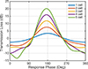 |
Figure 5. Theoretical dependence of the active metamaterial transmission loss on the unit cell response phase. |
As a consequence of the proportional control scheme, the inherent frequency responses of the individual active elements have a large impact on the metamaterial response. The microphone breakout board (SPW2430, Adafruit), which is used as both a cell component and for the upstream and downstream measurements, is assumed to have a flat response in its 100 Hz to 10 kHz range. Four speakers with different resonance frequencies of 850 (SP-1704, Soberton Inc.), 1300 (CS32-01W130-10-1X, Challenge Electronics), 1500 (CAC22-01W150-07-1X, Challenge Electronics), and 2200 Hz (CS28-02W220-05-1X, Challenge Electronics) were tested. Bode plots of the response of one representative speaker (CAC22) are shown in Figure 6. The response in Figure 6a is the received voltage from the downstream microphone relative to the driven voltage of the speaker. The phase was adjusted to remove the effect of the acoustic path length. Two lines are shown for both the magnitude and the phase, indicating transfer functions for a time-windowed pulse and a steady-state wave, respectively. The former can be useful for more general design, as it excludes the standing waves due to the finite waveguide length, which are dependent on the cell position. At the speaker resonant frequency, there is a clear peak in magnitude and steep drop in phase, centered on 180° (the speaker was wired to be out of phase with the driving voltage). This phase change will constrain the bandwidth for which loss occurs and will actually result in gain for frequencies at the tail ends of the resonant peak.
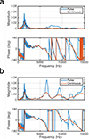 |
Figure 6. Experimental Bode plots of speaker acoustic pressure response (a) downstream and (b) feedback. |
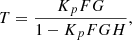
The response in Figure 6b is the feedback of the speaker and microphone in the same cell. While the same resonant peak is present in both responses, the feedback also includes significant high frequency content due to the short distance between the speaker and microphone. The closed loop frequency response T can be obtained as
 (4)
(4)
where G is the speaker downstream transfer function, H is the feedback, F is the filter transfer function, and K p is the proportional gain set by the potentiometer and rheostat (with a negative value for the scattered wave to be out of phase with the incident wave). The unit cell behavior is well approximated by the open loop frequency response at low frequencies for small gains, but high frequency peaks corresponding to positive feedback may result in instability. For a single unit cell, the stable gain limit can be determined through the Nyquist stability criterion, but for multiple cells, it is important to consider the cell interactions [16]. To increase the maximum stable gain, it was necessary to implement a low pass filter. A high pass filter was also needed due to the DC voltage offset of the analog microphone. First order filters were used with cutoff frequencies of 277 and 3770 Hz, minimizing the additional lag that would reduce the bandwidth of noise cancellation. The Bode plot of the bandpass filter is shown in Figure 7. The tradeoff for the low filter order is the weaker attenuation at high frequencies, which limits the stable gain.
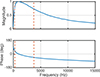 |
Figure 7. Experimental Bode plots of the analog bandpass filter with high pass frequency of 277 Hz and low pass frequency of 3770 Hz. |
The metamaterial transmission loss was assessed with different speakers and number of active cells for incident wave frequencies from 500 to 3000 Hz. The unit cell gains were set to the maximum stable values for the metamaterial of three cells. The total and background waves were separated by repeating measurements with the metamaterial inactive, so any passive leakage occurring due to its mounting was not included in the transmission loss. The full metamaterial, or individual cells, were made inactive by setting the gains of each cell amplifier to zero. The results are shown in Figure 8. The transmission losses in Figure 8a–8d correspond to the metamaterial configured with each of the different speakers that were tested, with one to three active cells. The results align with the modeled behavior in Figure 5. Peak transmission loss occurs at the resonance frequency where the response phase is approximately 180° and grows with the number of cells. Even though an isolated unit cell may be stable at a slightly higher gain than a cell with neighbors, the total transmission loss that can be achieved with multiple cells is still much greater.
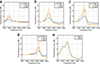 |
Figure 8. Transmission loss for the metamaterial configured with different speakers and number of unit cells: (a) SP-1704, (b) CS32, (c) CAC22, (d) CS28. (e) Transmission loss experimentally obtained for the metamaterial with three cells with both SP-1704 & CS32 speakers compared to the sum of the individual transmission losses in (a) & (b). |
Two speaker (SP-1704 & CS32) with different resonant frequencies (850 and 1300 Hz) were also mounted in a single unit cell, sharing a microphone, but with separate amplifiers. The transmission loss for three active cells is shown in Figure 8e and closely matches the sum of the transmission losses from the configurations with just the individual speakers. Because the different speakers do not share the same frequency responses, the bandwidth of noise absorption can be widened by incorporating multiple speakers without necessarily needing to lower the unit cell gains to maintain stability. The byproduct amplification of high frequency noise can be readily managed through passive methods, unlike the low frequencies targeted in the active metamaterial design.
While the transmission losses shown here are modest, there is significant room for optimization by increasing the number of unit cells and more carefully selecting the speakers and filters to achieve the ideal frequency response. Further work on tailoring the transfer functions is especially needed for realizing specific material properties, as in the reflectionless absorber, where the impressive performance may significantly degrade when the magnitudes and phases of both the monopole and dipole components do not closely match their ideal values. Possible approaches include the use of low latency electronics, strongly damped speakers, a combination of speakers with different resonances, and compensating filters that flatten the phase in the target band but outside of it may promote instability.
4 Conclusions
This work shows that active metamaterials can be implemented as highly effective and compact sound absorbers. The unit cells of the metamaterial are composed of independent sensor-driver pairs that promote scalability, i.e., more cells can be added to increase the area covered, bandwidth, or transmission loss without having to change the existing cell design or programming. The gain between the sensors and drivers in each pair are precomputed for desired effective acoustic properties leading to low dispersion structures. This approach contrasts with conventional controls methods used in existing noise cancellation devices that use complex, adaptive transfer functions realized with centralized controllers.
Remarkably, this work also shows that the fabricated metamaterial can switch functionality essentially instantaneously without any adverse effects such as ensuing instability. This property has been demonstrated here experimentally by repeatedly switching the metamaterial from absorber to transparent states, but can also be adapted for other applications that require very fast time modulation of material parameters recently associated with interesting physical phenomena.
Funding
This work was supported by the National Science Foundation under Grant No. CMMI-1942901 and by the Toyota Research Institute of North America.
Conflict of interest
The authors declare no competing interests.
Data availability statement
Data are available on request from the authors.
References
- T. Münzel, T. Gori, W. Babisch, M. Basner: European Heart Journal 35 (2014) 829. [Google Scholar]
- M. Long: Architectural Acoustics. Academic Press, 2005. [Google Scholar]
- M.J. Crocker: Handbook of Noise and Vibration Control. John Wiley & Sons, 2007. [Google Scholar]
- S.A. Cummer, J. Christensen, A. Alù: Nature Reviews Materials 1 (2016) 16001. [Google Scholar]
- T. Lee, T. Nomura, H. Iizuka: Scientific Reports 9 (2019) 13077. [Google Scholar]
- N. Gao, Z. Zhang, J. Deng, X. Guo, B. Cheng, H. Hou: Advanced Materials Technologies 7 (2022) 2100698. [Google Scholar]
- A. Arjunan, A. Baroutaji, J. Robinson, A. Vance, A. Arafat: Building and Environment 251 (2024) 111250. [Google Scholar]
- M. Reynolds, S. Daley: Smart Materials and Structures 23 (2014) 045030. [Google Scholar]
- K.-C. Chen, C.-Y. Chang, S.M. Kuo: IOP Conference Series: Materials Science and Engineering 237 (2017) 012015. [Google Scholar]
- B.-I. Popa, Y. Zhai, H.-S. Kwon: Nature Communications 9 (2018) 5299. [Google Scholar]
- B.-I. Popa, L. Zigoneanu, S.A. Cummer: Physical Review B 88 (2013) 024303. [Google Scholar]
- Y. Zhai, H.-S. Kwon, B.-I. Popa: Physical Review B 99 (2019) 220301. [Google Scholar]
- C. Cho, X. Wen, N. Park, J. Li: Nature Communications 11 (2020) 251. [Google Scholar]
- Y. Zhai, H.-S. Kwon, B.-I. Popa: Physical Review Applied 16 (2021) 034023. [Google Scholar]
- D.A. Kovacevich, B.-I. Popa: Applied Physics Letters 121 (2022) 101701. [Google Scholar]
- D.A. Kovacevich, K. Grosh, B.-I. Popa: Physical Review Applied 21 (2024) L051002. [Google Scholar]
- D.A. Kovacevich, B.-I. Popa: Smart Materials and Structures (2024). https://doi.org/10.1088/1361-665X/ad7550. [Google Scholar]
- D.A. Kovacevich, B.-I. Popa: Physical Review B 104 (2021) 134304. [Google Scholar]
- A.M. Baz: Journal of Vibration and Acoustics 132 (2010). https://doi.org/10.1115/1.4000983. [Google Scholar]
- W. Akl, A. Baz: Journal of Applied Physics 112 (2012) 084912. [Google Scholar]
- N. Zhen, R.-R. Huang, S.-W. Fan, Y.-F. Wang, Y.-S. Wang: npj Acoustics 1 (2025) 7. [Google Scholar]
- R. Ghaffarivardavagh, J. Nikolajczyk, S. Anderson, X. Zhang: Physical Review B 99 (2019) 024302. [Google Scholar]
- T. Lee, T. Nomura, E.M. Dede, H. Iizuka: Applied Physics Letters 116 (2020) 214101. [Google Scholar]
- P.A. Nelson, S.J. Elliott: Active Control of Sound, Paperback edn., 4. print. edn. Academic Press, San Diego, 2000. [Google Scholar]
- S.D. Snyder, C.H. Hansen: Journal of the Acoustical Society of America 86 (1989) 184. [Google Scholar]
- J. Cheer, S. Daley, C. McCormick: Smart Materials and Structures 26 (2017) 025032. [Google Scholar]
- G.M. Hernandez: Physical Review Applied 25 (2026). https://doi.org/10.1103/crg1-lp6y. [Google Scholar]
Cite this article as: Kovacevich D.A. Kustin J. Kwon H.-S. Lee T. Flynn M. & Popa B.-I. 2026. Noise mitigation with active acoustic metamaterials. Acta Acustica, 10, 34. https://doi.org/10.1051/aacus/2026037.
All Tables
All Figures
|
Figure 1. (a) Schematic of the experimental setup showing a medium of effective bulk modulus B and mass density ρ placed in a 2D waveguide and ensonified by an external speaker. (b) Programmable metamaterial realization of an effective medium with on-demand macroscopic effective B and ρ. (c) Photo of unit cell with the labeled microphones Mi and speakers Si, where |
| In the text | |
|
Figure 2. Time domain acoustic pressure measured in the empty waveguide (top) and with the time-modulated programmable metamaterial (bottom). The right pressure fields (transparent state) were measured 1.67 ms later than the left fields (absorber state), i.e., half the modulation period. |
| In the text | |
|
Figure 3. Time domain acoustic pressures (incident, active response, and total) measured at a point in the transmitted region beyond the metamaterial for different on/off modulation frequencies: (a) continuously on, (b) f 0/8 = 150 Hz, and (c) f 0/4 = 300 Hz. |
| In the text | |
|
Figure 4. (a) Schematic of the duct with a noise source at one end and the active metamaterial integrated into the walls in the midsection. An upstream and downstream microphone are used to determine transfer functions and the transmission loss. (b) The sensing and driving elements of the metamaterial are mounted in modular unit cells. (c) The active components of the unit cell. |
| In the text | |
|
Figure 5. Theoretical dependence of the active metamaterial transmission loss on the unit cell response phase. |
| In the text | |
|
Figure 6. Experimental Bode plots of speaker acoustic pressure response (a) downstream and (b) feedback. |
| In the text | |
|
Figure 7. Experimental Bode plots of the analog bandpass filter with high pass frequency of 277 Hz and low pass frequency of 3770 Hz. |
| In the text | |
|
Figure 8. Transmission loss for the metamaterial configured with different speakers and number of unit cells: (a) SP-1704, (b) CS32, (c) CAC22, (d) CS28. (e) Transmission loss experimentally obtained for the metamaterial with three cells with both SP-1704 & CS32 speakers compared to the sum of the individual transmission losses in (a) & (b). |
| In the text | |
Current usage metrics show cumulative count of Article Views (full-text article views including HTML views, PDF and ePub downloads, according to the available data) and Abstracts Views on Vision4Press platform.
Data correspond to usage on the plateform after 2015. The current usage metrics is available 48-96 hours after online publication and is updated daily on week days.
Initial download of the metrics may take a while.