| Issue |
Acta Acust.
Volume 9, 2025
|
|
|---|---|---|
| Article Number | 84 | |
| Number of page(s) | 13 | |
| Section | Building Acoustics | |
| DOI | https://doi.org/10.1051/aacus/2025070 | |
| Published online | 21 January 2026 | |
Scientific Article
Prediction of rainfall noise radiated by sandwich panels using the Finite Transfer Matrix Method
Acoustics Research Unit, University of Liverpool, Liverpool, L69 7ZN, UK
* Corresponding author: This email address is being protected from spambots. You need JavaScript enabled to view it.
Received:
2
September
2025
Accepted:
5
December
2025
Abstract
Multilayer elements, such as sandwich panels, are often used to form the roof of a building or car; hence validated prediction models are needed to determine the sound radiated by them during rainfall. To calculate the radiation efficiency of a sandwich panel formed from two plates and a porous material, the Finite Transfer Matrix Method (FTMM) has been used with an order-reduced integral equation and an additional term to account for nearfield radiation because, in comparison with homogeneous plates, sandwich panels tend to have high damping. Transfer mobility measurements on the sandwich panel showed that vibrational energy was concentrated near the point of excitation due to the panel being highly damped, and confirmed the validity of the limp porous material model for the foam that was used as the porous material. Experimental validation of the prediction models used artificial rain with drops impacting at approximately terminal velocity. This demonstrated that it was necessary to include the effect of nearfield radiation in the overall radiation efficiency. An assessment of existing empirical and semi-empirical models for the time-dependent force applied by liquid water drops showed that for this application of artificial rain in the laboratory it was reasonable to assume a dry surface when predicting the structure-borne sound power input.
Key words: Rain noise / Sandwich panel / Transfer matrix method
© The Author(s), Published by EDP Sciences, 2026
 This is an Open Access article distributed under the terms of the Creative Commons Attribution License (https://creativecommons.org/licenses/by/4.0), which permits unrestricted use, distribution, and reproduction in any medium, provided the original work is properly cited.
1 Introduction
Rainfall on lightweight roofing or roof windows in buildings can significantly increase the sound pressure level above background noise in the rooms below. Similarly, in automotive cabins there can be high sound pressure levels due to rain falling upon a panoramic glass roof, a multilayer metal roof, or the front and rear windshields. As the sound pressure level inside electric cars is generally lower than cars with combustion engines, rain noise becomes of increased importance for passenger comfort. During the design phase, prediction of the sound radiated by the roof due to natural rainfall is necessary to identify and avoid any adverse effects on speech intelligibility, comfort, and listening conditions for the occupants.
Lightweight roof structures in buildings and automobiles are often multilayer elements such as sandwich panels. These sandwich panels are typically formed from thin plates that, in isolation, have high modal densities and low damping, but when they are combined on either side of a porous interlayer they produce a sandwich panel which has high structural damping. Kou et al. [1] note that for a single plate with a moderately high loss factor of 5% to 10%, the radiation efficiency can be increased by 4 to 6 dB below the critical frequency; this can be attributed to significant sound radiation from the nearfield with point excitation [2]. Nearfield radiation can therefore be expected to be relevant to sandwich panels. Hence this paper focuses on the prediction of the vibrational response and sound radiation from such a sandwich panel that is excited by rainfall. The initial step in predicting rainfall noise requires a model for the force applied by a liquid water drop impact. Previous work by the authors has experimentally quantified these forces with drops impacting at a range of velocities up to terminal velocity [3] and developed empirical and semi-empirical models to estimate the structure-borne sound power input from artificial and natural rainfall [4]. These models were developed and validated using drops falling onto a single pane of glass and can be adapted to account for the inclination angle of a roof [4]. They are also shown to be more accurate than the idealised model of a paraboloid drop shape for the drop impact. The subsequent step involves the prediction of vibration transmission and sound radiation due to the point force excitation applied by rain drops and is the focus of this paper.
To predict the sound radiated by multilayer elements, prediction models based on Statistical Energy Analysis (SEA) sometimes use an equivalent damping to account for the noise control treatment [5]. This approach includes the mass effect of the whole structure via a smeared added mass by assuming that the layers are homogeneous although the effect of stiffness is usually neglected in the prediction model, and this can cause errors at low frequencies [6]. An alternative model, the Transfer Matrix Method (TMM) is well-suited to multilayer elements when it can be assumed that the layers are of infinite extent, or when a spatial windowing technique [7] can be used to account for edge diffraction due to the finite size of the element. As with SEA, TMM can take advantage of the spatial and temporal incoherence of rainfall excitation, which can be analysed conveniently in the frequency and wavenumber domain. TMM has previously been used by Guigou et al. [8] with multilayer elements to predict rainfall noise using the paraboloidal drop shape model. Comparisons with a modal model and SEA for double glazing indicated that the infinite plate assumption in TMM underestimates the sound radiation unless TMM is used to calculate the velocity level, and another model is used for the radiation efficiency of a finite plate. TMM predictions were also carried out for a sandwich panel, but this led to underestimates of the measured sound power in the low-frequency range, and when TMM was used with the radiation efficiency of a finite plate, the sound radiation was overestimated over the majority of the frequency range. Hence the current paper seeks to separately validate the structure-borne power input from the rainfall to the upper plate of the sandwich panel, the prediction of vibration transmission between the two plates that form the panel and the sound radiation by the lower plate of the sandwich panel. Schmid et al. [9] investigated the prediction of radiated sound power with artificial rain in the laboratory and compared three different radiation models on a single sheet of glass for which simply supported boundaries were assumed. Two of these models accounted for the location of raindrop impacts; however, all three models gave sound intensity levels that fluctuated within a few decibels of each other below the critical frequency. This indicated that the force locations were not critical for artificial rain on this glass plate, as is commonly assumed for “rain-on-the-roof” excitation. One of the models was a modal version of TMM (mTMM) that could account for plate modes arising from simply supported boundary conditions. This model has potential for multilayer elements such as thermal glazing where individual glass panes have relatively low damping although the assumption of this idealised boundary condition may not be appropriate for all glazing. It is hypothesised that for sandwich panels that are highly damped and formed from thin plates with high modal densities, the consideration of plate modes in the model due to the boundary conditions is not essential between 50 and 5k Hz; this is confirmed by the results for the sandwich panel in the current paper.
This paper carries out experimental validation of prediction models to investigate the importance of nearfield radiation from a sandwich panel that is excited by liquid water drops falling near terminal velocity. The sandwich panel is assumed to be formed from two thin plates with a porous material as the core because these are typically highly damped. The prediction model uses TMM in a form suited to finite size plates, which is referred to as the Finite Transfer Matrix Method (FTMM), and includes a modification to account for nearfield radiation from a sandwich panel. The force applied by a drop upon impact is highest when it falls at terminal velocity; hence, to assess nearfield radiation that is relevant to natural rain this drop velocity is used in the experimental validation. The availability of other empirical models for the force from a drop impacting at a velocity which is lower than terminal velocity [3, 4] means that the model in this paper can also be used to assess the importance of the nearfield in measurements with artificial rain that are used to characterise rain noise in the laboratory.
2 Theory for sound radiation from point force excitation of a sandwich panel
2.1 Transfer Matrix Method
TMM allows calculation of sound propagation across multilayer elements where each layer of stratified media is considered to be homogeneous, isotropic and laterally infinite. Generalized TMM theory for modelling acoustic fields in stratified media with porous materials as well as fluid and solid elastic layers was introduced by Brouard et al. [10]. In vibroacoustics, a general framework for TMM with different multilayer media is given by Allard and Atalla [5] for acoustical and mechanical excitation.
The sandwich panel considered in this paper is formed by a soft, porous foam in-between two elastic plates – see Figure 1. A limp porous material model is used for the foam [5] and the criterion proposed by Doutres et al. [11] are used in Section 4.1 to support the choice of this model.
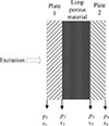 |
Figure 1. Diagram of the sandwich panel indicating the notation of the pressure and velocity at the boundary of each layer. |
Assuming excitation of plate 1 with a distributed pressure, p
1, the aim is to calculate the velocity, v
4, on plate 2 from which the radiated sound power can be calculated. The transfer matrix [T] relates the input ![Mathematical equation: $ {\Big[} \begin{array}{c} {p_1} \\ {v_1} \end{array} {\Big]} $](/articles/aacus/full_html/2025/01/aacus250131/aacus250131-eq2.gif) to the output
to the output ![Mathematical equation: $ {\Big[} \begin{array}{c} {p_4} \\ {v_4} \end{array} {\Big]} $](/articles/aacus/full_html/2025/01/aacus250131/aacus250131-eq3.gif) according to
according to
![Mathematical equation: $$ \begin{aligned} {\left[ \begin{array}{c} {p_1} \\ {v_1} \end{array} \right]} = {\left[ \begin{array}{c} {T}\end{array} \right]}{\left[ \begin{array}{c} {p_4} \\ {v_4} \end{array} \right]} = {\left[ \begin{array}{c} {T_{p1}}\end{array} \right]} {\left[ \begin{array}{c} {T_{\rm l}}\end{array} \right]} {\left[ \begin{array}{c} {T_{p2}}\end{array} \right]}{\left[ \begin{array}{c} {p_4} \\ {v_4} \end{array} \right]}. \end{aligned} $$](/articles/aacus/full_html/2025/01/aacus250131/aacus250131-eq4.gif) (1)
(1)
The elements of [T] are given by Allard and Atalla [5]
 (2)
(2)
![Mathematical equation: $$ \begin{aligned} T_{12}=&- Z_{\mathrm{s2} } \Bigg [\cos {\left(k_{\mathrm{l} } h\right)} - \frac{{i}\, Z_{\mathrm{s1} }\, k_{\mathrm{l} } \, \sin {\left(k_{\mathrm{l} } h\right)}}{\omega \, \rho _{\mathrm{l} }} \Bigg ] \nonumber \\& - Z_{\mathrm{s1} } \cos {\left(k_{\mathrm{l} } h\right)} + \frac{{i}\, \omega \, \rho _{\mathrm{l} } \, \sin {\left(k_{\mathrm{l} } h\right)}}{k_{\mathrm{l} }} \end{aligned} $$](/articles/aacus/full_html/2025/01/aacus250131/aacus250131-eq7.gif) (3)
(3)
 (4)
(4)
 (5)
(5)
where ω is the angular frequency, h is the thickness of the porous material, ρ l is the density of the porous material, Z s is the mechanical impedance of the elastic plate, and k l is the wavenumber for the porous material.
Using the equivalent fluid approach with a limp porous material model [5], the wavenumber for the compressional wave is calculated from the effective bulk modulus, K eq and is given by
 (6)
(6)
and the effective density, ρ limp, is given by
 (7)
(7)
in which ρ l is the density of the porous material, ϕ is the porosity of the porous material, ρ 0 is the density of air and ρ eq is given by
![Mathematical equation: $$ \begin{aligned} \rho _{\mathrm{eq} } = {\left[ {\phi \rho _0 + \rho _{\mathrm{a} } - \frac{i \, \sigma _0 \, \phi ^2 \, G(\omega )}{\omega } } \right]}/{\phi ^2} \end{aligned} $$](/articles/aacus/full_html/2025/01/aacus250131/aacus250131-eq12.gif) (8)
(8)
where σ 0 is the flow resistivity of the porous material and the inertial coupling term for air as a low viscosity fluid is given by
 (9)
(9)
and the Johnson et al. model [12] gives the term G(ω) as
 (10)
(10)
where Λ is the viscous characteristic length, q 0 = ς/σ 0, ς is the viscosity, α ∞ is the tortuosity, and ν = ς/ρ 0.
The effective bulk modulus, K eq = R/ϕ 2 where
 (11)
(11)
and the Champoux–Allard model [13] is used to give
 (12)
(12)
in which ν′=ν/Pr0 2, Pr0 is the Prandtl number, and Λ′ is the thermal characteristic length.
The next step is to apply force excitation, f(x, y, ω), on plate 1, for which the plate response is described by
 (13)
(13)
where w is the displacement, B is the bending stiffness and ρ s is the mass per unit area. Therefore equation (1) can be rewritten as
![Mathematical equation: $$ \begin{aligned} \begin{bmatrix}f + p_1 \\v_1\end{bmatrix}=[T]\begin{bmatrix}p_4 \\v_4\end{bmatrix}. \end{aligned} $$](/articles/aacus/full_html/2025/01/aacus250131/aacus250131-eq18.gif) (14)
(14)
The radiation efficiency of an infinite plate on the emission side, σ E, is the same as on the receiver side which is σ R, as given by
 (15)
(15)
where c 0 is the speed of sound in air and k 0 is the wavenumber in air.
The plate wavenumber, k f, can be written in terms of the x- and y-wavenumber components, k x and k y , as
 (16)
(16)
From equations (14) and (15), the velocity on the receiver side of the multilayer structure is obtained as
 (17)
(17)
where Z TMM is the impedance of the sandwich panel seen from the source side as given by
 (18)
(18)
For plate 1 that is undergoing excitation, Parseval’s theorem relates its mean-square velocity, ⟨v 1 2⟩, in the spatial domain to the wavenumber domain velocity V 1(k x , k y ), using [5]
 (19)
(19)
where S is the area of the plate. For point force loading, the radiated sound power, W rad, can then be determined from [5]
 (20)
(20)
2.2 Point force loading from liquid water drops
The impact from an artificial or real raindrop is considered here as point force excitation. Using a wave-based approach [6], the spatial domain load can be represented in the wavenumber domain using a Fourier integral transform as
![Mathematical equation: $$ \begin{aligned} F{\left(k_x, k_y, \omega \right)}&= \int _{-\infty }^{+\infty }\int _{-\infty }^{+\infty } f(x, y, \omega )\nonumber \\&\quad \times \exp {\left[-{i} {\left(k_x x + k_y y\right)}\right]} \,\mathrm{d} x\,\mathrm{d} y. \end{aligned} $$](/articles/aacus/full_html/2025/01/aacus250131/aacus250131-eq25.gif) (21)
(21)
To estimate the radiated sound power from point excitation over an area, the input pressure or the impact force distribution is assumed to be temporally random and spatially uncorrelated. Here it is assumed that the applied force position randomly varies over time so that spatial-temporal coupling can be ignored, then the force can be written as [14]:
 (22)
(22)
where f s(x, y) and f t(t) denote the spatial and temporal components of the force loading respectively. The assumption relating to the spatially uncorrelated force can be expressed as:
 (23)
(23)
where (x 0, y 0) is the excitation position.
The auto-spectrum of the point force excitation can then be obtained as:
 (24)
(24)
where N is the number of drop impacts per second and |F(ω)|2 is the autospectrum of a single raindrop impact.
The experimental validation with artificial rain in this paper is based upon raindrops representing “heavy rain” with diameters of ≈4.5 mm for which two force models are considered that account for the angle of inclination of the plate. These are the angle-corrected empirical model and an angle-corrected semi-empirical model.
For 4.5 mm diameter drops, the time-dependent force for a drop impacting at terminal velocity onto an inclined plate with or without a water layer can be calculated using the following angle-corrected empirical model [3, 4]:
![Mathematical equation: $$ \begin{aligned} f(t) = C_{\mathrm{A} } \, \exp {\left[- \frac{{\left(\ln (1000 t) + \alpha _{\mathrm{A} }\right)}^2}{\beta _{\mathrm{A} }^2} \right]} \end{aligned} $$](/articles/aacus/full_html/2025/01/aacus250131/aacus250131-eq29.gif) (25)
(25)
where C A, α A and β A are empirical constants. For 4.5 mm drops at terminal velocity that fall onto a plate inclined at 30°, these constants are given in Table 1. These have been derived from the data in reference [3] for 4.5 mm drops at terminal velocity, vT, assuming that the normal component of the drop velocity on a plate inclined at 30° is then vTcos(π/6) [4]. One of the uncertainties involved in estimating the force from drops during steady rainfall is whether there exists a shallow water layer of depth, d, on the surface of the plate during each drop impact. Compared to a dry plate, the presence of a shallow water layer tends to increase the force at low-frequencies and reduce it at high frequencies [3]. Previous work on a 6 mm glass plate indicated that for rainfall rates between 24 and 30 mm/h it is reasonable to consider the plate surface as being dry when estimating the force. Predictions for a dry surface and with a 1 mm water layer are made in this paper to gather more evidence on this aspect.
Angle-corrected empirical model: Constants for 4.5 mm drops travelling at terminal velocity when impacting a plate inclined at 30°.
Using the angle-corrected semi-empirical model [4] for 4.5 mm drops, the time-dependent force for a drop impacting with a drop velocity component, vd, n, that is perpendicular to the plate surface (with or without a water layer) is calculated using:
![Mathematical equation: $$ \begin{aligned} f(t) =&C \sqrt{\frac{t \, v_{\mathrm{d,n} }}{10^{-3} \, \tau _{\text{ SE}} \, D_{\mathrm{d} }}}\nonumber \\&\times \exp \!{\left[-{\left(\frac{t \, v_{\mathrm{d,n} }}{10^{-3} \, \tau \, D_{\mathrm{d} }}\right)}^\alpha \right]} \, 10^{-6} \, \rho _{\mathrm{w} } \, D_{\mathrm{d} }^2 \, v_{\mathrm{d,n} }^2 \end{aligned} $$](/articles/aacus/full_html/2025/01/aacus250131/aacus250131-eq30.gif) (26)
(26)
and
 (27)
(27)
where C and τ are empirical constants, θ is the angle of inclination of the plate, ρ w is the drop density, and D d is the drop diameter. For the drop velocity of 9.09 m/s that is used in the experimental work in this paper (which is ≈99% of the terminal velocity), these constants have been re-calculated using equations (20) and (21) in reference [4] to be C = 2.348 and τ = 0.364.
2.3 Radiation efficiency
TMM is widely used to predict the response of structures with attached noise control layers in single- and double-walls due to structure-borne or airborne excitation. However, the infinite plate assumption can lead to considerable errors in the prediction at low- and mid-frequencies because of the influence of edge diffraction on sound radiation below the critical frequency [7]. Hence, rather than use equation (15) for an infinite plate to calculate the radiation efficiency, σ R(k x , k y , ω), for substitution in equation (20), a computationally efficient, reduced order integral is used to calculate σ R, F(k x , k y , ω) for a finite plate assuming in-plane baffles as given by Yu and Hopkins [15]:
![Mathematical equation: $$ \begin{aligned}&\sigma _{\mathrm{R,F} }(k_x, k_y, \omega ) = \mathfrak{R} \Biggl \{ \frac{2 \, {i} \, k_0}{\pi \, S} \int _0^{L_y} \Biggl ( \frac{L_x L_y \pi }{2} - L_y R - L_x R\nonumber \\&\qquad + \frac{R^2}{2} \Biggr ) J_0(k_{\mathrm{f} } R) \, e^{-{i} k_0 R} \,\mathrm{d}R \nonumber \\&\qquad + \frac{2 \, {i} \, k_{0}}{\pi \, S} \int _{L_{y}}^{L_{x}} \Biggl (L_{x}L_{y}\,\arcsin \!{\left(\frac{L_{y}}{R}\right)} \nonumber \\&\qquad - \frac{L_{y}^{2}}{2}+ L_{x}\sqrt{R^{2}-L_{y}^{2}}- L_{x}R \Biggr )\, J_{0}\!{\left(k_{\mathrm{f} } R\right)}\, e^{-{i} k_{0} R}\, \mathrm{d} R\nonumber \\&\qquad + \frac{2 \, {i} \, k_{0}}{\pi \, S}\int _{L_{x}}^{\sqrt{L_{x}^{2}+L_{y}^{2}}}\Biggl [L_{x}L_{y}{\left(\arcsin \!{\left(\frac{L_{y}}{R}\right)} - \arccos \!{\left(\frac{L_{x}}{R}\right)}\right)}\nonumber \\&\qquad + L_{y}\sqrt{R^{2}-L_{x}^{2}} + L_{x}\sqrt{R^{2}-L_{y}^{2}}- \tfrac{1}{2}{\left(L_{x}^{2}+L_{y}^{2}+R^{2}\right)} \Biggr ]\nonumber \\&\qquad \times J_{0}\!{\left(k_{\mathrm{f} } R\right)}\, e^{-{i} k_{0} R}\, \mathrm{d} R \Biggr \} \end{aligned} $$](/articles/aacus/full_html/2025/01/aacus250131/aacus250131-eq32.gif) (28)
(28)
where the trace wavenumber, k
f, is replaced by  , and the x- and y-directions of the rectangular plate are arranged such that L
x
≥ L
y
.
, and the x- and y-directions of the rectangular plate are arranged such that L
x
≥ L
y
.
The advantages of using this formulation are that it maintains the accuracy of the spatial windowing approach of Villot et al. [7] but increases the computational efficiency whilst avoiding singularities and the simplifying assumption of a square rather than a rectangular plate [15]. It also maintains the integral approach in the wavenumber domain for the radiated sound power in equation (20). No assumption is made of any idealised boundary condition (e.g. simply supported) because the plates are assumed to have sufficiently high modal density that this will not have a significant effect on the sound radiation. The next step is to remove the assumption of in-plane baffles in the calculation of the radiation efficiency because this is not a common type of baffle in buildings or in cars. Below the critical frequency, a correction factor, Q ψ , for angled baffles can be estimated where ψ is the internal angle in radians between the radiating plate and the surrounding baffles using [16]
 (29)
(29)
This correction factor assumes that the rectangular plate has the same baffle angle at all four edges. In the experimental work in this paper, the baffle angles are different at each of the four edges of the radiating panel: 90°, 120°, 90° and 60°. Therefore, an average correction factor is used, given by
 (30)
(30)
The radiation efficiency from TMM using the finite size correction along with the option to include different baffle configurations (Eqs. (28)–(30)) will be referred to in this paper as σ FTMM, which is given by
 (31)
(31)
For comparison with FTMM, the radiation efficiency formulae from the modal approach of Leppington et al. [16–18] are considered for an isotropic, rectangular plate with simply supported boundaries. These are asymptotic results based on the product of the acoustic wavenumber and either of the plate dimensions tending towards infinity. This results in an average value for all plate modes within a frequency band and assumes a high modal density and continuous wavenumbers. The Leppington radiation efficiency equations are given by:
![Mathematical equation: $$ \begin{aligned} \sigma = {{\left\{ \begin{array}{ll} {\left( 0.5 - \frac{0.15 \, L_{y}}{L_{x}} \right)} \sqrt{k_{0} \, L_{y}}&f = f_{c} \\ \frac{L_{x} + L_{y}}{\pi \, S \, k_{0} \, \mu \sqrt{\mu ^{2} - 1}} {\left[ \ln \!{\left( \frac{\mu + 1}{\mu - 1} \right)} + \frac{2 \, \mu }{\mu ^{2} - 1} \right]}\\ \times {\left[ C_{\mathrm{BC} } \, C_{\mathrm{OB} } - \mu ^{-8}{\left(C_{\mathrm{BC} } \, C_{\mathrm{OB} } - 1\right)} \right]}&f < f_{c} \\ \frac{1}{\sqrt{1 - \mu ^{2}}}&f > f_{c} \end{array}\right.}} \end{aligned} $$](/articles/aacus/full_html/2025/01/aacus250131/aacus250131-eq37.gif) (32)
(32)
where f c is the critical frequency, C BC is a constant for the plate boundary conditions (C BC = 1 for simply supported boundaries which were assumed to be a reasonable approximation in the experimental setup), C OB is a constant for the orientation of the baffles that surround the edges of the plate (where C OB = Q ψ from equation (30), μ = f c/f, and the x- and y-directions of the rectangular plate are arranged such that L x ≥ L y .
2.4 Nearfield radiation
For a single plate that is highly damped, the nearfield radiation from point force excitation can be equally important, or more important than sound radiation from the vibration field over the entire surface of the plate below the critical frequency [18–20]. For an infinite plate and point force excitation with an rms force, F rms, the sound power radiated by the nearfield, W n, is given by Cremer et al. [19]
 (33)
(33)
and the power radiated by the bending wave field, W b, is
 (34)
(34)
where η is the loss factor of the plate, Z
dp is the driving-point impedance, which for an infinite plate is  , and ⟨v
2⟩ is the spatial average mean-square velocity.
, and ⟨v
2⟩ is the spatial average mean-square velocity.
The nearfield power can now be written in terms of the bending wave power
 (35)
(35)
which allows the total radiated power to be given in terms of an equivalent radiation efficiency for the nearfield, σ n, where
 (36)
(36)
Hence, the equivalent radiation efficiency for the nearfield is
 (37)
(37)
The next step is to consider the plates that form the sandwich panel as these are highly damped and can also be considered as infinite plates. Point force excitation on plate 1 will give rise to a uniformly distributed force per unit area, p 3, (i.e. pressure) on plate 2 for which the displacement on the inner surface, w 3, is governed by the following bending wave equation [20]
![Mathematical equation: $$ \begin{aligned} B_{2} {\left[ {\left(k_{x}^{2} + k_{y}^{2}\right)}^{2} - k_{\mathrm{b,2} }^{4} \right]} \, w_{3}{\left(k_{x}, k_{y}\right)} = p_{3}{\left(k_{x}, k_{y}, \omega \right)} \end{aligned} $$](/articles/aacus/full_html/2025/01/aacus250131/aacus250131-eq44.gif) (38)
(38)
and the radiated sound pressure can be expressed as
 (39)
(39)
which can be re-written using equation (38) as
![Mathematical equation: $$ \begin{aligned} p_{4}{\left(k_{x}, k_{y}, \omega \right)} =&\frac{{i} \, \omega ^{2} \, \rho _{0}}{\sqrt{k_{0}^{2} - k_{x}^{2} - k_{y}^{2}}}\nonumber \\&\times \frac{p_{3}(k_{x}, k_{y}, \omega )}{B_{2} {\left[ {\left(k_{x}^{2} + k_{y}^{2}\right)}^{2} - k_{\mathrm{b,2} }^{4} \right]}} \end{aligned} $$](/articles/aacus/full_html/2025/01/aacus250131/aacus250131-eq46.gif) (40)
(40)
where ![Mathematical equation: $ k_{\mathrm{b,2}} = \sqrt{\omega} \, \sqrt[4]{\frac{\rho_{\mathrm{s2}}}{B_{2}}} $](/articles/aacus/full_html/2025/01/aacus250131/aacus250131-eq47.gif) .
.
As with the initial derivation for a single plate, the next step is to calculate the radiated power from plate 2 of the sandwich panel for the nearfield and the bending wave field. The power radiated by the nearfield, W n, is
![Mathematical equation: $$ \begin{aligned} W_{\mathrm{n} } =&\frac{1}{2} \, \mathfrak{R} {\left\{ p_{4} \, v_{4}^{*}\right\} } = \frac{1}{2} \frac{\rho _{0} \, c_{0} \, \omega ^{2} \, k_{0}}{\sqrt{k_{0}^{2} - k_{x}^{2} - k_{y}^{2}}} \nonumber \\&\times {\left( \frac{p_{3}{\left(k_{x}, k_{y}\right)}}{B_{2} {\left[ (k_{x}^{2} + k_{y}^{2})^{2} - k_{\mathrm{b,2} }^{4} \right]}} \right)}^{2} \end{aligned} $$](/articles/aacus/full_html/2025/01/aacus250131/aacus250131-eq48.gif) (41)
(41)
and when f ≪ f c
 (42)
(42)
The power radiated from the surface of plate 2 is given by
 (43)
(43)
and the power input to the plate must equal the dissipated power due to its loss factor, hence
 (44)
(44)
from which the mean-square velocity is used to determine the radiated power as
 (45)
(45)
The ratio of powers radiated from the driving point and the reverberant vibration field can now be calculated using equations (42) and (45) which removes p 3 2 and gives
 (46)
(46)
where k
f is equal to  . The equivalent radiation efficiency for nearfield radiation is then given by
 (47)
(47)
Note that by implementing an integral average of equation (47) in the domain k f < k 0, it simplifies to give equation (37).
The overall radiation efficiency of a damped point-excited plate for FTMM in equation (20) can now be calculated using
 (48)
(48)
where σ R, F is the FTMM radiation efficiency calculated using equation (28) and σ n is calculated from equation (47). Accounting for the baffle arrangement (Eq. (30)) gives
![Mathematical equation: $$ \begin{aligned}&\sigma (k_{x}, k_{y}, \omega ) = \frac{1}{4} \sum _{j=1}^{4} Q_{\psi _{j}} \, \mathfrak{R} \Biggl \{ \frac{2 i k_{0}}{\pi S} \int _{0}^{L_{{y}}} \Biggl (\frac{L_{{x}} L_{{y}} \pi }{2} \nonumber \\&\qquad - L_{{y}} R - L_{{x}} R + \frac{R^{2}}{2} \Biggr ) J_{0} {\left(k_{\mathrm{f} } R\right)} e^{-i k_{0} R} \, \mathrm{d} R \nonumber \\&\qquad + \frac{2 i k_{0}}{\pi S} \int _{L_{{y}}}^{L_{{x}}} \Biggl ( L_{{x}} L_{{y}} \arcsin {\left(\frac{L_{{y}}}{R}\right)} - \frac{L_{{y}}^{2}}{2} \nonumber \\&\qquad + L_{{x}} \sqrt{R^{2} - L_{{y}}^{2}} - L_{{x}} R \Biggr ) J_{0}\!{\left(k_{\mathrm{f} } R\right)} e^{-i k_{0} R} \, \mathrm{d} R \nonumber \\&\qquad + \frac{2 i k_{0}}{\pi S} \int _{L_{{x}}}^{\sqrt{L_{{x}}^{2} + L_{{y}}^{2}}} \Biggl [ L_{{x}} L_{{y}} {\left( \arcsin {\left(\frac{L_{{y}}}{R}\right)} \right.}\nonumber \\&\qquad - {\left.\arccos {\left(\frac{L_{{x}}}{R}\right)} \right)} + L_{{y}} \sqrt{R^{2} - L_{{x}}^{2}} \nonumber \\&\qquad +L_{{x}} \sqrt{R^{2} - L_{{y}}^{2}} - \frac{1}{2}{\left(L_{{x}}^{2} + L_{{y}}^{2} + R^{2}\right)} \Biggr ]\nonumber \\&\qquad \times J_{0} {\left(k_{\mathrm{f} } R\right)} e^{-i k_{0} R} \, \mathrm{d} R \Biggr \}\nonumber \\&\qquad + \frac{4 \, c_{0} \, \eta }{\pi \, f_{\mathrm{c} }} \frac{1}{\sqrt{k_{0}^{2} - k_{\mathrm{f} }^{2}}} \quad \mathrm{for} \ f < f_{\mathrm{c} }. \end{aligned} $$](/articles/aacus/full_html/2025/01/aacus250131/aacus250131-eq57.gif) (49)
(49)
Substituting equations (18), (24) and (49) into equation (20) gives the radiated sound power for the finite-size sandwich panel under point force excitation that includes sound radiation from nearfields.
3 Laboratory experiments
3.1 Sandwich panel
The sandwich panel used in the experimental work was formed from three layers: a 1.5 mm thick Aluminium plate, 11.4 mm thick open-cell polyurethane foam and a 2.9 mm thick Polymethyl Methacrylate (Perspex) plate. These three layers were bonded together using spots of cyanoacrylate glue. The intention was not to replicate a specific roof used in a car or building but to ensure that all the material properties of the components were known or could be measured.
The frame holding the sandwich panel rested upon a “baffle box” which was constructed from a double layer of 18 mm chipboard separated by a 12 mm air gap (see Fig. 2a). This box was used to reduce extraneous background noise when making the sound intensity measurements inside the baffle box.
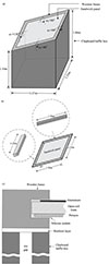 |
Figure 2. Sandwich panel and testing arrangement: (a) Orientation of the sandwich panel when attached to the baffle box, (b) Wooden frame holding the sandwich panel, (c) Fixing of the sandwich panel into the frame that rests upon the baffle box. |
The sandwich panel had dimensions of 1.5 m × 1.25 m and was enclosed around the edges in a wooden frame (see Fig. 2b). The sandwich panel was angled at 30° to allow the water to run off.
Flanking transmission from the sandwich panel to the sides of the box was minimized by including a layer of resilient foam around the top of the baffle box (see Fig. 2c).
3.2 Transfer mobility measurements
To assess the dynamic properties of the sandwich panel, FFT analysis was carried out with 1 Hz line spacing to determine transfer mobilities; these are the complex ratio of velocity at different receiving points on one plate to a force applied to the other plate. A force hammer with a Brüel & Kjær Type 8200 force transducer and steel tip was used at five random excitation positions on the Aluminium plate with a 9 × 11 grid of accelerometer positions on the Perspex plate (125 mm grid spacing with all positions at least 125 mm from the edge of the frame).
3.3 Sound intensity measurements
The sound intensity radiated by the sandwich panel was measured using a sound intensity probe (Brüel & Kjær Type 3519, Type 4183 phase matched microphones with 50 mm and 12 mm spacers) positioned over a grid of discrete points as required in ISO 9614-1 [21] using one-third octave bands from 50 to 5k Hz.
3.4 Plate velocity measurements
The spatial average velocity was measured using six accelerometers (Brüel & Kjær DeltaTron Type 4517) located randomly over the plate surface.
3.5 Artificial rainfall set-up
The laboratory set-up used a rain box to provide artificial rainfall as described in Yu and Hopkins [4]. The sandwich panel was orientated so that the artificial rain would fall onto the side with the Aluminium plate. The floor of the baffle box was lined with ≈0.8 m absorbent material to facilitate sound intensity measurements.
The measured drop velocity was 9.09 m/s from a drop height of 11.4 m and a rainfall rate of 24 mm/h as used in previous experimental work to assess a 6 mm glass plate [4]. This drop velocity was approximately equal to the terminal velocity of 9.17 m/s that was achieved with a 15 m drop height in previous work [3]. The water drops were measured to have a 4.6 mm diameter; this was sufficiently close to the 4.5 mm drops that it was appropriate to use the model for the time-dependent force developed in previous work [3, 4].
4 Results
4.1 Sandwich panel properties
The material properties for the two plates that form the sandwich panel are given in Table 2. The Young’s modulus of Perspex was frequency-dependent; hence it was experimentally determined at bending eigenfrequencies of Perspex beam samples (two samples for each of the following lengths: 0.1, 0.2, 0.25, 0.29 and 0.3 m) by measuring the point input impedance at their centre according to the procedures described in ISO 16940 [22]. The measurement results for the Young’s modulus and loss factor are shown in Figure 3. Over the range of eigenfrequencies from 42 Hz to 7256 Hz, the average loss factor of the Perspex is 0.073 and the curve fit for the Young’s modulus, E, that depends on frequency, f, is described by the following relationship:
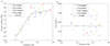 |
Figure 3. Measured material properties for the 2.9 mm thick Perspex beam samples with different lengths: (a) Young’s modulus. (b) Loss factor. |
Plate properties.
 (50)
(50)
The properties of the porous foam were measured by Matelys [23]. This used the approach of Jaouen et al. [24] for porosity, flow resistivity, tortuosity, viscous characteristic length and thermal characteristic length, and the two-sample measurement method in ISO 18437-5 [25] for the Young’s modulus, Poisson’s ratio and loss factor. These properties are summarised in Table 3 and are also used to assess whether the assumption of a limp porous material model was appropriate by using the criterion developed by Doutres et al. [11]. This is based on the parameter for the Frame Stiffness Influence (FSI), and the first quarter-wavelength resonance frequency of the frameborne wave, fr. Doutres et al. proposed an upper limit of 0.16 for the magnitude of FSI (based on the confidence rate of 95% from 256 simulated porous materials) over the frequency range from fr/2 to 2fr. This criterion was satisfied for the foam which had calculated values that were less than 0.1; hence the limp frame model was used.
Foam properties.
The total loss factor of the sandwich panel is not required as input data for the TMM model; however, measurements were taken to illustrate the relatively high damping of the panel compared to the component plates. From Table 2, the Perspex has a significantly higher internal loss factor than Aluminium but when both are combined to make the sandwich panel, the total loss factor was sufficiently high that clear decay curves could not be measured with forward or reverse filter analysis [16] to determine structural reverberation times. Therefore, estimates of the total loss factor were determined from driving-point mobility measurements using 3 dB down points from individual panel resonances; these indicated that the total loss factor up to 5k Hz was typically in the range 0.1 to 0.3.
4.2 Transfer mobility
Figure 4 shows the contour plots of the transfer mobility in terms of the magnitude in decibels (using 20 lg) that have been normalised to the highest value at narrow band frequencies of 125, 500, 1k and 5k Hz. Due to the high damping, the contour plots show that high levels of vibrational energy on the sandwich panel tend to be concentrated around the area on the opposite side to the excitation position. This indicates that it is reasonable to consider nearfield radiation for this sandwich panel below the critical frequencies of the Perspex and Aluminium plates, which are estimated to be ≈10k Hz and ≈8.5k Hz respectively.
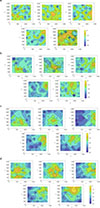 |
Figure 4. Contour plot of the transfer mobility (magnitude) in decibels normalized to the highest value on the surface. The response positions for the accelerometer are on the Perspex plate with five different excitation positions for the force hammer (indicated by the red * symbol) on the Aluminium plate. Results are shown at the following narrow band frequencies: (a) 125 Hz, (b) 500 Hz, (c) 1k Hz and (d) 5k Hz. |
Figure 5 compares the spatial-average transfer mobility from the grid of accelerometer positions on the Perspex plate with the prediction from TMM (Eqs. (17) and (18)) in narrow bands. Note that FTMM only applies to the predictions involving sound radiation. The spatial-average value is calculated from the five excitation positions and 99 receiver positions using
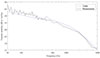 |
Figure 5. Comparison of the spatial-average transfer mobility from measurements on the sandwich panel with TMM. Excitation is on the Aluminium plate (source side) with accelerometer positions on the Perspex plate (receiving side). |
 (51)
(51)
The agreement between the measurements and the prediction model is typically within 3 dB between 50 Hz and 5k Hz. This validates the use of TMM with a limp porous material model for the foam in this sandwich panel. The absence of strong modal resonances in the response also confirms that there is no need to use a prediction model that consider the modes which occur due to the boundary conditions. The shallow peak in the TMM prediction at 381 Hz corresponds to the mass-spring-mass resonance due to the air contained within the porous material although this is not visible in the measurement.
4.3 Artificial rainfall
With the artificial rainfall, Figure 6 compares the measured velocity level on the Perspex plate with predictions from FTMM and the empirical or semi-empirical model for the structure-borne sound power input on the Aluminium plate. The angle-corrected empirical model is shown for a dry surface and a surface with a 1 mm water layer. On average, the assumption of a dry surface in the empirical and semi-empirical models is reasonable over the entire frequency range although the semi-empirical model shows slightly closer agreement with the measurement (within 2 dB) below 1.5 kHz. The assumption of a 1 mm water layer overestimates the force below 1k Hz and underestimates the force above 1k Hz indicating that it is not necessary to account for any residual water on the surface of the sandwich panel.
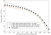 |
Figure 6. Velocity level measured on the Perspex plate of the sandwich panel when excited by artificial rainfall (4.6 mm drop diameter, 9.09 m/s drop velocity, 24 mm/h rainfall rate): comparison of measurements with FTMM predictions. |
The next step is to predict the radiated sound power with and without the inclusion of nearfield radiation by using the measured plate velocity and the predicted radiation efficiencies from Leppington et al. and FTMM. The predictions are compared with the measured radiated power in Figure 7. These results allow an assessment of the predicted radiation efficiencies without incurring any additional uncertainty from the predicted structure-borne sound power input of the artificial rainfall. It is seen that the inclusion of the nearfield in the prediction model leads to higher radiated sound power levels. The measured radiated power tends to show closest agreement with the predictions that include the nearfield radiation; this is particularly evident below 250 Hz and above 500 Hz. The differences in the predicted values with or without the nearfield range from 2.3 to 6.1 dB for the Leppington radiation efficiency and 3.4 to 7.5 dB for the FTMM radiation efficiency. This indicates the importance of the nearfield radiation. Note that in previous work using artificial rain on a 6 mm glass plate (for which the total loss factor was 0.022) the effect of including the nearfield would have been negligible (< 1 dB) but with this highly damped sandwich panel, the effect of the nearfield is significant.
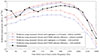 |
Figure 7. Comparison of the measured and predicted sound power radiated by the sandwich panel when excited by artificial rainfall (4.6 mm drop diameter, 9.09 m/s drop velocity, 24 mm/h rainfall rate). Prediction models use the measured plate velocity and the radiation efficiency from Leppington et al. or FTMM with or without nearfield radiation. |
When including the nearfield, the difference between the Leppington and FTMM radiation efficiencies only ranged from 0.2 to 1.8 dB; hence it was not possible to identify one of the two radiation efficiency approaches as being more appropriate for this particular panel. However, previous comparisons of Leppington et al, the order-reduced integral equation and other prediction formulae for a homogeneous glass plate indicate that the approach of Leppington et al. might overestimate the sound radiation below the critical frequency for some plates [15].
Figure 8 compares the measured sound power radiated from the sandwich panel with predictions from FTMM incorporating nearfield radiation that use either the angle-corrected empirical or semi-empirical models for the structure-borne sound power input due to artificial rainfall. Between 80 Hz and 630 Hz the measured sound power is closest to the empirical or semi-empirical model for the dry surface and between 1.25k Hz and 3.15k Hz it is closest to the empirical model for the dry surface. The assumption of a 1 mm water layer is not justified by the measurements; hence combined with previous evidence from experiments on a 6 mm glass plate with the same type of artificial rainfall, it is reasonable to assume a dry surface when predicting rain noise at this rainfall rate.
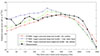 |
Figure 8. Comparison of the measured and predicted sound power radiated by the sandwich panel when excited by artificial rainfall (4.6 mm drop diameter, 9.09 m/s drop velocity, 24 mm/h rainfall rate). Prediction model uses FTMM with nearfield radiation. |
Empirical theory is available to calculate the structure-borne sound power input from natural rain as well as artificial rain [4]; hence the approach in this paper can also be used to calculate rain noise from multilayer roofs in situ with natural rain.
5 Conclusions
The sound radiated by a sandwich panel that is excited by artificial rain has been predicted using the finite transfer matrix method. Material properties of the sandwich panel were experimentally quantified and close agreement between measurements and predictions of the average transfer mobility gave experimental validation of the limp porous material model used for the foam. Transfer mobility measurements also showed that the vibrational energy was concentrated around the point excitation position on the opposite side of the sandwich panel. The radiation efficiency of the sandwich panel accounted for the finite panel size and was calculated using an order-reduced integral equation as well as the Leppington et al. formulae. Due to the high damping of sandwich panels, this was combined with a prediction of the nearfield radiation. Experimental validation with artificial rain indicated that it was necessary to include the nearfield radiation and that it was reasonable to assume a dry surface when predicting the structure-borne sound power input. Due to the importance of the nearfield radiation the accuracy of the two approaches to determine the radiation efficiency was found to be similar.
Acknowledgments
The authors are very grateful to Dr. Gary Seiffert for all his help with designing and building the experimental set-ups, and to Dr. Luc Jaouen and Dr. Matt Edwards from Matelys for the experimental characterisation of the foam.
Conflicts of interest
The authors declare that they have no conflicts of interest in relation to this article.
Data availability statement
Data are available on request from the authors.
Author contribution statement
Yicheng Yu: Conceptualization, Formal analysis, Investigation, Methodology, Validation, Visualization, Writing – original draft, Writing – revised draft, Carl Hopkins: Conceptualization, Funding acquisition, Investigation, Methodology, Supervision, Writing – original draft, Writing – revised draft.
References
- Y. Kou, B. Liu, J. Tian: Radiation efficiency of damped plates. The Journal of the Acoustical Society of America 137, 2 (2015) 1032–1035. [Google Scholar]
- G. Xie, D. Thompson, C. Jones: The radiation efficiency of baffled plates and strips. Journal of Sound and Vibration 280, 1, 2 (2005) 181–209. [Google Scholar]
- Y. Yu, C. Hopkins: Experimental determination of forces applied by liquid water drops at high drop velocities impacting a glass plate with and without a shallow water layer using wavelet deconvolution. Experiments in Fluids 59 (2018) 1–23. [Google Scholar]
- Y. Yu, C. Hopkins: Empirical models for the structure-borne sound power input from artificial and natural rainfall. Applied Acoustics 162 (2020) 107199. [Google Scholar]
- J. Allard, N. Atalla: Propagation of Sound in Porous Media: Modelling Sound Absorbing Materials. 2nd edn. John Wiley and Sons, 2009. [Google Scholar]
- D. Rhazi, N. Atalla: Transfer matrix modelling of the vibroacoustic response of multi-materials structures under mechanical excitation. Journal of Sound and Vibration 329, 13 (2010) 2532–2546. [Google Scholar]
- M. Villot, C. Guigou, L. Gagliardini: Predicting the acoustical radiation of finite size multi-layered structures by applying spatial windowing on infinite structures. Journal of Sound and Vibration 245, 3 (2001) 433–455. [Google Scholar]
- C. Guigou-Carter, M. Villot: Study of simulated rainfall noise on multi-layered systems, in: Proceedings of EURONOISE 2003, 2003. [Google Scholar]
- G. Schmid, M.J. Kingan, L. Panton, G.R. Willmott, Y. Yang, C. Decraene, E. Reynders, A. Hall: On the measurement and prediction of rainfall noise. Applied Acoustics 171 (2021) 107636. [Google Scholar]
- B. Brouard, D. Lafarge, J.F. Allard: A general method of modelling sound propagation in layered media. Journal of Sound and Vibration 183, 1 (1995) 129–142. [CrossRef] [Google Scholar]
- O. Doutres, N. Dauchez, J.-M. Génevaux, O. Dazel: Validity of the limp model for porous materials: a criterion based on the Biot theory. The Journal of the Acoustical Society of America 122, 4 (2007) 2038–2048. [Google Scholar]
- D.L. Johnson, J. Koplik, R. Dashen: Theory of dynamic permeability and tortuosity in fluid-saturated porous media. Journal of Fluid Mechanics 176 (1987) 379–402. [Google Scholar]
- Y. Champoux, J.F. Allard: Dynamic tortuosity and bulk modulus in air-saturated porous media. Journal of Applied Physics 70, 4 (1991) 1975–1979. [CrossRef] [Google Scholar]
- J.L. Guyader, C. Boisson, C. Lesueur: Energy transmission in finite coupled plates, part I: theory. Journal of Sound and Vibration 81, 1 (1982) 81–92. [Google Scholar]
- Y. Yu, C. Hopkins: Reduced order integration for the radiation efficiency of a rectangular plate. JASA Express Letters 1.6 (2021) 062801. [Google Scholar]
- F.G. Leppington, E.G. Broadbent, K. Heron: Acoustic radiation from rectangular panels with constrained edges. Proceedings of the Royal Society A 393, 1804 (1984) 67–84. [Google Scholar]
- F.G. Leppington, E.G. Broadbent, K. Heron: The acoustic radiation efficiency of rectangular panels. Proceedings of the Royal Society A 382, 1783 (1982) 245–271. [Google Scholar]
- C. Hopkins: Sound Insulation, Butterworth–Heinemann, 2007. [Google Scholar]
- L. Cremer, M. Heckl, E.E. Ungar: Structure-Borne Sound. Springer-Verlag, 1973. [Google Scholar]
- F.J. Fahy: Sound and Structural Vibration: Radiation, Transmission and Response. Academic Press, London, 1985. [Google Scholar]
- ISO 9614-1:1993 Acoustics – Determination of sound power levels of noise sources using sound intensity. Part 1: measurement at discrete points. International Organization for Standardization, 1993. [Google Scholar]
- ISO 16940:2008 Glass in building – Glazing and airborne sound insulation – Measurement of the mechanical impedance of laminated glass. International Organization for Standardization, 2008. [Google Scholar]
- L. Jaouen: Private Communication. October 2018. Matelys (www.matelys.com), France, 2018. [Google Scholar]
- L. Jaouen, E. Gourdon, P. Glé: Estimation of all six parameters of Johnson–Champoux–Allard–Lafarge model for acoustical porous materials from impedance tube measurements. The Journal of the Acoustical Society of America 148, 4 (2020) 1998–2005. [Google Scholar]
- ISO 18437-5:2011 Mechanical vibration and shock – Characterization of the dynamic mechanical properties of visco-elastic materials. Part 5: Poisson ratio based on comparison between measurements and finite element analysis. International Organization for Standardization, 2011. [Google Scholar]
Cite this article as: Yu Y. … Hopkins C. 2025. Prediction of rainfall noise radiated by sandwich panels using the Finite Transfer Matrix Method. Acta Acustica, 9, 84. https://doi.org/10.1051/aacus/2025070.
All Tables
Angle-corrected empirical model: Constants for 4.5 mm drops travelling at terminal velocity when impacting a plate inclined at 30°.
All Figures
|
Figure 1. Diagram of the sandwich panel indicating the notation of the pressure and velocity at the boundary of each layer. |
| In the text | |
|
Figure 2. Sandwich panel and testing arrangement: (a) Orientation of the sandwich panel when attached to the baffle box, (b) Wooden frame holding the sandwich panel, (c) Fixing of the sandwich panel into the frame that rests upon the baffle box. |
| In the text | |
|
Figure 3. Measured material properties for the 2.9 mm thick Perspex beam samples with different lengths: (a) Young’s modulus. (b) Loss factor. |
| In the text | |
|
Figure 4. Contour plot of the transfer mobility (magnitude) in decibels normalized to the highest value on the surface. The response positions for the accelerometer are on the Perspex plate with five different excitation positions for the force hammer (indicated by the red * symbol) on the Aluminium plate. Results are shown at the following narrow band frequencies: (a) 125 Hz, (b) 500 Hz, (c) 1k Hz and (d) 5k Hz. |
| In the text | |
|
Figure 5. Comparison of the spatial-average transfer mobility from measurements on the sandwich panel with TMM. Excitation is on the Aluminium plate (source side) with accelerometer positions on the Perspex plate (receiving side). |
| In the text | |
|
Figure 6. Velocity level measured on the Perspex plate of the sandwich panel when excited by artificial rainfall (4.6 mm drop diameter, 9.09 m/s drop velocity, 24 mm/h rainfall rate): comparison of measurements with FTMM predictions. |
| In the text | |
|
Figure 7. Comparison of the measured and predicted sound power radiated by the sandwich panel when excited by artificial rainfall (4.6 mm drop diameter, 9.09 m/s drop velocity, 24 mm/h rainfall rate). Prediction models use the measured plate velocity and the radiation efficiency from Leppington et al. or FTMM with or without nearfield radiation. |
| In the text | |
|
Figure 8. Comparison of the measured and predicted sound power radiated by the sandwich panel when excited by artificial rainfall (4.6 mm drop diameter, 9.09 m/s drop velocity, 24 mm/h rainfall rate). Prediction model uses FTMM with nearfield radiation. |
| In the text | |
Current usage metrics show cumulative count of Article Views (full-text article views including HTML views, PDF and ePub downloads, according to the available data) and Abstracts Views on Vision4Press platform.
Data correspond to usage on the plateform after 2015. The current usage metrics is available 48-96 hours after online publication and is updated daily on week days.
Initial download of the metrics may take a while.