


| Issue |
Acta Acust.
Volume 10, 2026
|
|
|---|---|---|
| Article Number | 69 | |
| Number of page(s) | 10 | |
| Section | Hearing, Audiology and Psychoacoustics | |
| DOI | https://doi.org/10.1051/aacus/2026072 | |
| Published online | 24 July 2026 | |
Technical & Applied Article
Optimizing binaural cue measurement for an acoustic test fixture using a 3D-head shell
1
Fraunhofer Institute for Digital Media Technology IDMT, Branch Hearing, Speech and Audio Technology HSA, Oldenburg, Germany
2
Department of Medical Physics and Acoustics, Carl von Ossietzky Universität Oldenburg and Cluster of Excellence “Hearing4All”, Oldenburg, Germany
* Corresponding author: This email address is being protected from spambots. You need JavaScript enabled to view it.
Received:
9
July
2025
Accepted:
3
July
2026
Abstract
Although artificial heads based on the human anatomy are typically used to measure binaural cues in various scenarios, they usually do not provide sufficient acoustic insulation that becomes important, e.g., when measuring at low frequencies or with hearing protectors. For these purposes, an acoustic test fixture (ATF) with high acoustic insulation should be used. However, such ATFs do not reflect the human anatomy, which may affect measurements of binaural cues and other spatially separated sounds. This study investigated differences in interaural time and level differences measured with an artificial head with human anatomy and the GRAS ATF 45CA. The measurements took place inside an anechoic chamber with a circular array of 48 loudspeakers. Moreover, a mountable head consisting of two 3D-printed shells for the ATF based on a KEMAR head was designed to approximate plausible head anatomy while preserving the advantages of an ATF. Binaural cues were also measured with the ATF and attached head shells. The results indicate that differences in binaural cues between the artificial head and ATF largely depend on incident angle and frequency. The differences could be reduced with the additional head shells which make them a reasonable add-on for the ATF when measuring binaural cues.
Key words: Localization / Artificial head / Interaural cues / Horizontal plane / Acoustic test fixture
© The Author(s), Published by EDP Sciences, 2026
 This is an Open Access article distributed under the terms of the Creative Commons Attribution License (https://creativecommons.org/licenses/by/4.0), which permits unrestricted use, distribution, and reproduction in any medium, provided the original work is properly cited.
1 Introduction
Measurements with human subjects cannot be performed under hazardous conditions for the human ear, e.g., when assessing the properties of a hearing protection device (HPD) that needs to be measured at high sound pressure levels. In these cases, but also for modeling (and analysis) purposes as well as for regulatory verification, it is crucial to conduct technical measurements. However, only a few measurement devices allow for correct measurements by providing sufficient acoustic insulation that exceeds the insertion loss of the HPDs.
The acoustic test fixture (ATF) 45CA by the manufacturer GRAS Sound and Vibration is designed to meet the criteria of the international standard ISO 4869-3 [1] concerning a high acoustic insulation for measuring the insertion loss of mainly earmuffs, but also earplugs. A high acoustic insulation ensures that the levels measured with the ATF are solely due to the noise transmitted through the HPDs without contamination from ambient noise leaking to the microphones through sound transmission via the body of the ATF. The acoustic insulation is mainly achieved by a higher mass of the ATF that reduces vibrations of the ATF itself at high noise levels that could interfere with the measured sound. Additionally, it provides a better sealing in terms of large base plates where over-ear devices can be placed with a lower risk of leakage than at curved areas around the ears which may occur with more realistically shaped heads.
The ATF 45CA is also suited to test special HPDs like those with additional electronic functions such as hear-through settings according to EN 13819-3 [2] to assess their performance as specified in the appropriate product standard. In these cases, the high acoustic insulation is necessary to prevent the sound level induced by the earplugs from being adulterated by environmental sounds due to leakage or vibrations of the ATF itself. This is especially relevant for level-dependent devices. Apart from measurements of HPDs, and depending on configuration, the ATF also allows to measure sound quality of hearing aids, earphones and headphones up to 50 kHz according to IEC 60318-1 [3] or 60318-4 [4].
However, the 45CA comes with less realistic human anatomy. It consists of a robust metal cylinder with large base plates to reduce leakage, on which the ears are placed at the correct (average) distance. In contrast, artificial heads according to IEC 60318-7 [5] better represent the human anatomy of the entire head, and thus, the typical diffraction pattern and bending of sound waves due to the different human structural parts [6, 7]. Accordingly, those artificial heads are usually the first choice when measuring binaural parameters such as interaural level differences (ILDs) and interaural time differences (ITDs) which are the main features when assessing the azimuthal direction of arrival.
ITDs are driven by the diameter of the head including the distance of the two ears, and bending of the sound waves around the head. They can be exploited by the human binaural auditory system for frequencies up to approximately 1.5 kHz [8], because time / phase differences become ambiguous at higher frequencies. In contrast, ILDs are most prominent for high frequencies from 2.5 kHz upwards [8] because the head represents a shadowing obstacle for sound waves with shorter wavelengths. ILDs exhibit their typical pattern by the diffraction and scattering of the sound at the pinnae, head, shoulders and torso.
Several studies have shown that the existence or absence of human structures such as pinna, shoulders or torso in different artificial heads or (numerical) spherical heads influences measured and simulated head-related-transfer functions (HRTFs) as well as ILDs and ITDs [9–12]. Though a good agreement between HRTFs of different artificial head systems was shown in [10], and similar ITDs between a spherical head and a Knowles Electronics Manikin for Acoustic Research (KEMAR) were seen in [11], at least ILDs with a spherical head were typically underestimated compared to head measurement systems under test in former studies [11, 12]. Additionally, measurements with a stereo-microphone not only led to higher ITDs compared to human listeners but also very small ILDs without frequency-dependency [13]. Further comparisons of the localization performance of human subjects listening to recordings of several artificial heads showed no specific differences between the performance with the different devices in the horizontal plane except between those with torso compared to those artificial heads without torso [14, 15].
However, the ATF GRAS 45CA is neither a simple stereo microphone nor does it contain any more human structure except for the distance and placement of the ears. Accordingly, the influence of the ATF structure on binaural cues is unknown. Though the assessment of binaural cues is typically not the primary focus of measurements employing an ATF based on the standards, it is one of a few devices suitable for measurements with HPDs. Since HPDs have a huge influence on communication and situational awareness, including detection and localization of warning signals [16–18], it is not only crucial to test these aspects with human listeners, but also to have suitable measurement methods to technically measure, analyze, understand and model these effects.
The question arises of how to measure binaural cues with HPDs or other hearables. On the one hand, ATFs have a high acoustic insulation, but deviations from natural human head anatomy may impact binaural cue measurements. On the other hand, an artificial head with human structures allows for realistic binaural cue measurements, but might be affected by too low acoustic insulation, especially in use cases of HPDs. Although the manufacturer GRAS also sells an ATF type 45CB with high acoustic insulation for measurements with HPDs that already contains a head, this one is only intended for use with the American standard ANSI/ASA S12.42 [19]. No ATF currently combines a realistic human head representation with ISO 4869-3 conformity. Thus, this study aims to quantify the differences in binaural parameters measured with the ATF GRAS 45CA in conformity with ISO 4869 and the artificial head HMS II.3 from HEAD acoustics. Since the measurements revealed systematic differences between the two measurement devices, a head shell was designed and 3D-printed based on an openly available KEMAR artificial head from [20]. The purpose of the shell was to better approximate binaural cues when conducting measurements with the ATF 45CA similar to the ATF type 45CB already including a head. Accordingly, ILDs and ITDs were also measured with the mounted head shell.
2 Design of the head shell
The head shell was designed for the ATF GRAS 45CA using the CAD program Autodesk Fusion 360. Since this ATF is available with additional KEMAR pinnae, the head shell was constructed by modifying a 3D-scan of the KEMAR from [20] (Fig. 1a) for the sake of consistency. The torso of the KEMAR model was removed, and the head split into one rear and one frontal half to allow for mounting the head shell onto the ATF (Figs. 1b and 1c). Semicircular cutaways around the ears and neck of the ATF were added, as well as holes for the capillary equalization tubes and openings for the upper part of the ATF to mount over-ear devices with a headband. Around the ears, the head was bulged to fit around the large base plates of the ATF that are meant to reduce the risk of leakage. The head shells were 3D-printed with polylactic acid (PLA) fiber, the settings of three lines of filament (model’s wall) and 30% infill. The 3D-files are available at [21]. Foam rubber was adhered to the surface area of the borders for better sealing between the shells and the metal cylinder of the ATF. Four DIN 912 M5x80 screws with nuts were used to fasten the two shells together and fix them around the ATF. The M5 nuts were glued to the shell to prevent them from falling off during assembly.
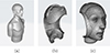 |
Figure 1. Models of the head and torso of the KEMAR by Braren and Fels [20] (a) and the rear (b) and frontal (c) head shell to be screwed together around the ATF. |
3 Evaluation
To evaluate the head shell and identify differences between the systems concerning binaural cues, the following three measurement systems were compared (see Fig. 2) by analyzing ITDs and ILDs for 48 azimuthal directions:
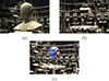 |
Figure 2. Measurement systems under test. (a) Artificial head, (b) ATF, (c) ATF with head shell. |
-
The artificial head HMS II.3 measurement system with shoulders by HEAD acoustics. This condition was used as a reference. The artificial head is equipped with anatomically shaped pinna simulators ITU type 3.3 [22] and an impedance simulator in conformity with IEC 60318-4 [4]. The geometry of the head and torso as well as the anatomically shaped pinna simulators comply with IEC 60318-7 [5].
-
The acoustic test fixture ATF 45CA-7 by GRAS Sound and Vibration. This configuration of the ATF is equipped with RA0045 externally polarized ear simulators in compliance with IEC 60318-4 [4] and the large standardized anthropometric KEMAR pinnae.
-
The same acoustic test fixture as in (b) with the additional 3D-printed head shell based on a KEMAR model.
3.1 Experimental setup
The measurements took place in an anechoic chamber with a background noise level of 18 dB(A). The room meets the conditions of an anechoic room down to 200 Hz and has a clear working area of 7.5 × 4.0 × 6.0 m3 (length × width × height). The artificial head and the ATF were placed on a custom-built stand covered in acoustic foam on a platform in the center of a circular array of 48 loudspeakers of type 8030B by Genelec with a radius of 2 m. The loudspeakers were spaced with an angular distance of 7.5° and placed 1.8 m above the floor. The stand for the measurement systems was adjustable in height to align the ear canals of the artificial head and ATF to the same height as the loudspeakers. D.O.Tec 32-channel MADI DA converters were connected to the loudspeakers and an RME MADIface XT audio interface which was controlled by a computer running MATLAB. The equipment was located in adjacent rooms to the anechoic room. A GRAS 12AQ with linear input was used as an additional amplifier for the microphone signals of both ears of the artificial head as well as of the ATF. The ears were calibrated with a GRAS 42AG multifunction sound calibrator at 1 kHz at 94 dB sound pressure level (SPL). The calibrator has a specified accuracy of ±0.2 dB at 94 dB SPL.
3.2 Stimuli
A linear sine sweep from 100 Hz to 8000 Hz with a duration of 1 s was played back to analyze ITDs, and pink noise with 5 s duration was used to calculate ILDs. The signals were sampled at 48 kHz and ramps of 50 ms (pink noise) or 5 ms (sweep) were applied at the start and end of the stimuli using a Hann window. Both stimuli were played back from each of the 48 loudspeakers and for all measurement systems at 70 and 80 dB(A) to confirm the linearity of all systems. A sound-level meter XL2 by NTi Audio was used to calibrate the levels of the audio signals. Prior to the measurements, the loudspeaker array was calibrated to produce an equal level from each direction at the listener’s position.
3.3 Analysis
ITDs and ILDs were calculated for each target direction and measurement system. ILDs were calculated using the recordings of the pink noise stimulus. Ear signals were processed using a third-octave bandpass filterbank with center frequencies ranging from 125 Hz to 10 kHz. The frequency-dependent ILDs were calculated for each bandpass filter as the difference between the sound pressure level at the left and the right ear. ITDs were calculated using the recordings of the sine sweep stimulus. First, the recordings were cut at 1500 Hz to analyze only the first part of the sweep that contains the relevant frequencies for ITDs in human listeners. This part of the recordings was additionally split into three sections (100–500 Hz, 500–1000 Hz and 1000–1500 Hz) to obtain a frequency-dependent analysis of ITDs. Second, the cross-correlation between both ear signals was calculated and the time lag producing the maximum of the cross-correlation function was used as an estimate of the ITD per frequency range.
ILDs and ITDs derived from the original recordings did not exactly produce zero ILDs and ITDs for 0° (front) and ±180° (back). Deviations most likely occurred due to a slight rotation of the devices when placing them on the stand in the measurement room. To align ITDs and ILDs with the target angle in a plausible way and for better comparison of the three measurement systems, two correction steps were conducted. First, the courses of ITDs and ILDs over target angle were aligned by determining the angle where ITDs were at 0 ms, and then shifting the ITD and ILD curves so that this point corresponded to 0°. Before this alignment, the courses of ILDs and ITDs showed a small shift suggesting a sound source coming from an angle of about 1.9° towards the left instead of 0° with the artificial head, and 2.5° towards the right with both measurements of the ATF.
After this first correction step, the ILDs measured with the artificial head still showed an offset of about 1.4 dB at 0° across all third-octave bands. The ILDs in the two ATF conditions were already symmetric around 0 dB ILD at 0°. Thus, as second correction step, the offset of the ILDs measured with the artificial head was compensated by shifting the course of ILDs by 1.4 dB. Subsequently, zero ITDs as well as ILDs for frontal and rear sound incidence were achieved for all three measurement systems. Due to the alignment along the angular axis, a linear interpolation between adjacent directions was applied to compare the results at the same incident angles correctly. The results were interpolated in steps of 0.1°.
3.4 Measurement uncertainty
Measurement uncertainty was assessed by measuring the ATF with the head shell twice with complete disassembly and repositioning on different days. The uncertainty was quantified using the root-mean-square (RMS) difference
 (1)
(1)
where N is the number of angle-frequency combinations (48 angles × 20 frequency bands = 960), and ILD1 and ILD2 are the ILDs from the first and second measurement, respectively. RMS was calculated overall and separately for each frequency band. Only the ATF with head shell was measured because of its complexity that provides a conservative upper bound for measurement uncertainty.
Subsequently, a conservative significance criterion was applied to assess whether observed ILD differences between measurement systems exceed measurement uncertainty. Differences were considered meaningful relative to measurement uncertainty when they exceeded twice the frequency-specific RMS error. This threshold was chosen to account for potential variability in the systems being compared. The percentage of angle-frequency combinations exceeding this threshold was calculated for each system comparison.
4 Results
The results at both levels differed by at most 0.2 dB, thus indicating linear behavior of all systems. In the following, the further analysis will only focus on the results obtained at 80 dB(A) based on a single measurement.
The ITDs were first calculated across the entire analyzed frequency range (100–1500 Hz) for each measurement system and incident angle from −180° to +180°. With the ATF (±0.71 ms), the maxima were somewhat lower than those with the artificial head (±0.73 ms). In contrast, the additional head shell increased the maxima to ±0.77 ms.
To assess frequency-dependent ITD behavior, the analysis was extended to three frequency ranges. The ITDs shown in Figure 3 were calculated for each measurement system, for incident angles from −180° to +180° and the frequency ranges 100–500 Hz (top), 500–1000 Hz (middle) and 1000–1500 Hz (bottom). Each curve is point symmetric around the origin at 0° and shows the largest absolute values for leftwards (−90°) and rightwards (90°) signals, while ITDs were 0 ms for signals from the front (0°) and back (±180°) after applying the offset correction described above. However, the absolute maximum values differed slightly between measurement systems and frequency ranges. The frequency-dependent analysis revealed decreasing maximum ITDs with increasing frequency for all systems, but with different magnitudes. The artificial head (solid line) showed the strongest decline (±0.89 to ±0.71 ms, 20% reduction), followed by the ATF with head shell (dashed line) showing a small decline (±0.81 to ±0.77 ms, 5%), and the original ATF (dotted line) with a minimal change (±0.73 to ±0.71 ms, 3%).
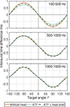 |
Figure 3. Interaural time differences measured in the three measurement systems for three frequency ranges 100–500 Hz (top), 500–1000 Hz (middle) and 1000–1500 Hz (bottom). |
The ILDs per incident angle and measurement system for third-octave bands with center frequencies from 125 Hz to 10 kHz are displayed in Figure 4. The results show symmetric ILD curves around 0° in all third-octave center frequencies and measurement systems with no ILDs for frontal (0°) and rear (±180°) signals (thanks to the offset correction described above). The (absolute) ILDs increased with higher frequency as well as with increasing laterality except for the troughs around ±90°. Those troughs appeared for frequencies between 1 kHz and 6 kHz in all three measurement systems. Although all measurement systems showed similar slopes, differences in the maximum absolute ILDs between the systems could be observed. The maximum absolute ILDs per third-octave band was highest with the artificial head (top panel), ranging from 1.2 dB for a center frequency of 125 Hz to 20.2 dB for 10 kHz, and lowest with the original ATF (middle panel, 1.1 to 18.7 dB). The additional head shell (bottom panel) led to intermediate maximum values (1.3 to 19.0 dB).
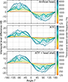 |
Figure 4. Interaural level differences per angle and third-octave band center frequency for the three measurement systems. |
A more detailed comparison between the results of the three conditions at certain incident angles and center frequencies is provided in Figure 5. The figure shows the ILD magnitudes per measurement system and third-octave center frequency between 125 Hz and 10 kHz for eight rightwards incident angles. The results for signals arriving from the left were similar and are not shown. Again, increasing ILDs with increasing frequency and laterality become visible. However, the ILDs of the ATF (dotted lines) were smaller in most bandpass filters than those of the artificial head (solid lines). Exceptions could be found at 2 kHz. In this frequency region, the ILDs of the ATF were larger than those of the artificial head for some incident angles. The smallest differences between both conditions could be found around 1 kHz at all incident angles. With the added head shell (dashed line), the differences of ILDs between the artificial head and the ATF were generally smaller, especially towards higher frequencies from 4 kHz upwards. At 2 kHz, however, where the ILDs with the ATF without head shell were already larger than with the artificial head, the ILDs even increased with the added head shell, e.g., at 90° and at 105° incident angle.
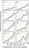 |
Figure 5. Absolute interaural level differences per third-octave center frequency for the three measurement systems and eight incident angles. |
To compare the exact differences between the ILDs with the artificial head and the two ATF conditions, Figure 6 shows the absolute differences between the ILDs with the artificial head and the original ATF (dotted line) and ATF with head shell (dashed line), respectively. The differences were calculated for all incident angles averaged over the 20 third-octave frequency bands in the range of 125 Hz to 10 kHz (left), and for all third-octave bands averaged over all 48 incident angles (right). In both parts of the figure, smaller differences in ILDs with the additional head shell compared to the original ATF can be seen. In general, the differences in ILDs clearly depended on incident angle and frequency. In both ATF conditions, the differences between ILDs increased with more laterality and tended near 0 dB for frontal and rear signals.
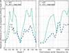 |
Figure 6. Absolute difference of interaural level differences between the ATF (dotted) and ATF with head shell (dashed) compared to the ILDs measured with the artificial head for all incident angles averaged over frequency (left) and for all third-octave bands averaged over incident angles (right). |
Concerning frequency, the largest differences with the original ATF could be found between 500 and 1000 Hz and from 4 kHz onwards. In contrast, the highest deviation with the additional head shell was at around 2 kHz. In the other frequency regions, the absolute differences between the artificial head and ATF with head were smaller than between artificial head and original ATF.
Considering all 48 angles and third-octave frequency bands between 125 Hz to 10 kHz without averaging (i.e., across all 960 individual combinations per condition), the maximum absolute error between ILDs with the artificial head and the original ATF (7.5 dB) was larger than between artificial head and ATF with head shell (6.0 dB). Similarly, the overall mean absolute error (calculated as the arithmetic mean across all 960 combinations) with the original ATF (1.5 dB) exceeded the error with the additional head shell (0.9 dB).
Test-retest measurements with the ATF with head shell under full repositioning conditions led to an RMS error of 0.4 dB across all angles and frequencies (Tab. 1). Frequency-dependent RMS errors ranged from 0.1 dB (200 Hz) to 0.7 dB (3150 Hz). The maximum observed difference between measurements was 2.6 dB at a single angle-frequency combination (105° at 3150 Hz). The systematic bias was negligible (0.02 dB overall).
Frequency-specific repeatability and significance metrics for ILD measurements across angles. RMS error derived from test-retest measurements (ATF with head shell, n = 2). Effect-to-error ratios (Eff/Err) correspond to the relation of mean absolute ILD difference (Fig. 6, right panel) to RMS error.
The ILD differences shown in Figure 6 were compared against twice the frequency-specific RMS error as a conservative threshold to assess statistical significance (effect-to-error ratio). This analysis revealed that 61% of angle-frequency combinations of ILD differences between artificial head and the original ATF exceeded the significance criterion with effect-to-error ratios of 4.0. The additional head shell decreased the number of significant ILD differences to 42% and the effect-to-error ratio to 2.4. The frequency-specific analysis showed strongest effects at low to medium frequencies (315–1250 Hz: effect-to-error ratios 4–9), decreasing at higher frequencies (8–10 kHz: 2–4). At 500 Hz, 77–94% of all angles showed significant differences across comparisons, while at 3.15 kHz, only 27–44% exceeded the threshold (not shown).
5 Discussion
Across all frequency ranges (100–1500 Hz), the ITDs with the original ATF were similar to those of the artificial head, though marginally smaller. In contrast, the head shell led to a larger maximum ITD. These small deviations can be explained by differences in acoustic path lengths. The shortest distance between the ear canal entrance points of the artificial head is about 29.5 cm as approximately measured with a standard measuring tape. For the original ATF, it is slightly lower (about 29.0 cm) while it is slightly larger when adding the head shells (about 31.0 cm). These findings are similar to those of [11] who found similar ITDs with a KEMAR and a spherical head with the same pathlength between both ears.
The frequency-dependent ITD analysis revealed that maximum ITD values decreased with increasing frequency for all systems, consistent with established literature [23]. However, the magnitude of this frequency-dependent decline differed between the measurement systems. The artificial head (i.e., the only condition with shoulders) exhibited the strongest ITD reduction across frequency ranges, while the ATF conditions showed progressively smaller frequency-dependent changes, with the original ATF leading to the smallest differences. These differences in frequency-dependent ITD decline align with numerical modeling by Cai et al. [24], who demonstrated that torso or shoulder structures amplify frequency-dependent differences in ITDs. However, both the latter study and the current findings are in contrast to the measurements by Kuhn [23], where an additional torso diminished the frequency-dependency of ITDs. A possible explanation for these different patterns is the methodology of the measurements. While the current study and the study by Cai et al. [24] used microphones positioned in the ear canal capturing the complete acoustic path, Kuhn [23] used microphones mounted on the head surface that primarily capture head diffraction, excluding pinna effects.
In contrast to ITDs, ILDs were generally smaller for the original ATF as well as for the additional head shell compared to the ILDs with the artificial head. However, all three measurement systems showed increasing ILDs and angle-dependency with increasing frequency as known from, e.g., [25, 26]. The differences between the systems confirm the expectation of dissimilar binaural cues due to the missing and/or altered human anatomy which strongly influences scattering and reflections [12, 13]. With the original ATF as well as with the head shell, the absolute differences compared to ILDs with the artificial head were largest for lateral angles and very small for frontal and rear sources.
Adding the head shells to the ATF systematically decreased the difference in ILD compared to the artificial head, especially towards more lateral signals and higher frequencies. Quantitatively, the overall mean absolute ILD error between the artificial head and original ATF was 1.5 dB (maximum: 7.5 dB across all angles and frequencies). This was reduced to 0.9 dB (maximum: 6.0 dB) with the head shell, demonstrating the benefit of using the head shell for measurements of binaural cues. Nevertheless, some differences between the artificial head and ATF with head shell remained.
A notable difference occurred at 2 kHz where both ATF conditions exhibited larger ILDs than the artificial head, particularly at lateral angles. These lower ILDs in the artificial head can be explained by destructive interferences between direct sound and shoulder reflections as presumed by Burkhard and Sachs [27]. They demonstrated that the presence of a torso leads to a frequency-specific reduction in sound pressure level. Assuming this effect occurs mainly at the ipsilateral ear, it could also lead to a reduction in ILD. The frequency of this reduction area increases with decreasing ear-to-shoulder distance. The artificial head used in the current study has a neck length of approximately 15–16 cm, which is shorter than the shortest neck reported by Burkhard and Sachs [27] (16.3 cm). This is consistent with a shift of the frequency region from the reported 1.4 kHz in [27] to a slightly higher frequency in the current study. Both ATF conditions have missing shoulders and thus, do not exhibit this frequency-specific effect. This could explain why their ILDs exceed those of the artificial head near 2 kHz.
One reason for further smaller deviations in ILDs between measurement systems could be the comparison of two different human-like heads: the artificial head by HEAD acoustics and the KEMAR. However, Møller et al. [14] and Minnaar et al. [15] compared the localization performance of participants when listening to a real sound field or a recording of the same sound field with seven artificial heads. Specific differences between localization performance with the different artificial heads were mainly observed between those with and without torso [14], and statistically significant differences occurred only for median plane errors [15]. Though localization performance was similar between the seven heads, binaural cues were not measured and could have been slightly different as in our observations.
The largest structural differences between the ATF with head shell and the artificial head were the missing shoulders at the ATF as well as the large base plates of the ATF cylinder. The frequency-specific ILD pattern near 2 kHz can be attributed to the missing shoulders, as explained above through the destructive interferences described by Burkhard and Sachs [27]. However, the role of the ATF’s base plates in the observed ILD differences remains unclear and may contribute to the overall magnitude differences between systems, though the systematic frequency-specific effects appear dominated by the absence of shoulder structures. Concerning the general impact of missing shoulders, Fedtke [10] did not find remarkable differences in HRTFs between different head measurement systems with and without shoulders for frequencies up to 8 kHz. Accordingly, except for the specific 2 kHz effect, the missing shoulders at the ATF should not have had a considerable influence on the measured ILDs. This is supported by Genuit [6] who found that shoulders are mainly important for localization in the median plane, and the head most important for localizing in the horizontal plane. This leads to an important limitation of the head shell. The current results are limited to the horizontal plane only. Thus, the ATF might need an additional add-on in terms of shoulders or torso if the binaural cues in the median plane shall be assessed as well. Beyond enabling median plane measurements, the addition of shoulders could also further minimize the remaining differences between artificial head and ATF with head shell, in particular those near 2 kHz. Future research should therefore systematically investigate how additional shoulders contribute to binaural cues in both the median and horizontal plane. The question remains how closely altered HRTFs are related to altered ILDs. A monaural HRTF on the opposite side of the head than the incident sound shows a low-pass filter and comb filter effects due to the group time delay around the head as seen in [6]. Accordingly, altered HRTFs due to missing structures of the head measurement system might have an impact on ILDs.
The separate analysis of measurement uncertainty of the ATF with head shell showed excellent repeatability between two measurements (0.4 dB RMS error). The observed ILD differences between the artificial head and both ATF conditions partly exceeded measurement uncertainty substantially with effect-to-error ratios up to 10.4 at certain frequencies. Accordingly, the observed ILD differences between measurement systems relied on acoustical differences, not measurement uncertainty. The frequency-specific analysis revealed that ILD differences between artificial head and original ATF were significantly higher than measurement uncertainty in all frequencies. Similar results were obtained with the additional head shell except for 3.15 kHz suggesting reduced statistical power in this frequency range due to higher positioning sensitivity. Largest ILD differences between artificial head and ATF with head shell, however, were found at 2–2.5 kHz where the effect-to-error ratio of 3–4 indicated reliable results. Overall, the additional head shell reduced effect-to-error ratio as well as the percentage of significant ILD differences between measurements with the artificial head and ATF across most of the frequency range. This demonstrates that the head shell fulfills its intended function of improving binaural cue measurements although some differences still remain.
The assessment of measurement uncertainty only focused on the ATF with head shell under full repositioning conditions because this condition represents the most complex setup and thus, provides an upper bound for interpreting differences between measurement systems. The original ATF is expected to show equal or better repeatability due to the reduced complexity without an additional head shell. For the artificial head, Buchholz et al. [28] measured in a comparable setup using tonal stimuli (1250 Hz, n = 5 measurements) and reported an RMS error of 0.7 dB which is approximately twice the frequency-specific RMS error of the ATF with head shell at 1250 Hz (0.3 dB). At this frequency, the observed ILD difference between artificial head and ATF with head shell (0.6 dB) is comparable to the artificial head’s repeatability (0.7 dB) indicating that the head shell effectively reduces ILD differences to near the measurement uncertainty for the artificial head. However, the higher repeatability error in the artificial head might be related to a higher positioning sensitivity for tonal compared to broadband stimuli due to frequency-specific interference patterns and spectral notches arising from diffraction around the head geometry. Considering the comparison of artificial head and original ATF, ILD differences significantly exceed measurement uncertainty of the artificial head. Overall, the differences between systems across all frequencies (0.9–1.5 dB) are larger than both repeatability estimates (0.4–0.7 dB), supporting the validity of cross-system comparisons. Considering ITD measurements, the temporal resolution (21 μs at 48 kHz sampling rate) is negligible compared to the measured values (±0.71–0.77 ms).
Overall, the ATF 45CA in combination with the proposed head shell is an interesting alternative to the ATF type 45CB that already contains a head, but is only intended for use with the American standard ANSI/ASA S12.42 [19]. The head shell is suitable for all companies and researchers using the ATF 45CA in compliance with ISO 4869-3, EN 13819-3, IEC 60318-1 or 60318-4 [1–4] and who are also interested in a low-priced reproducible add-on for more reliable binaural measurements in the horizontal plane with their ATF.
6 Conclusions
This paper compared binaural cues measured with an artificial head based on human anatomy with the ATF 45CA by GRAS Sound and Vibration with high acoustic insulation. Additionally, a 3D-printable head shell for the ATF based on a KEMAR that aligns with the human anatomy was designed, and the impact of adding this head shell to the ATF on binaural cues was assessed. ITDs were very similar for all measurement systems across frequency ranges, with differences primarily explained by variations in acoustic path length. However, the artificial head exhibited a stronger frequency-dependent ITD decline compared to the ATF conditions, consistent with shoulder-related diffraction effects. ILDs followed a similar pattern for all systems, but were systematically smaller with the original ATF compared to the artificial head. ILDs with the head shell were more aligned to those measured with the artificial head than with the original ATF. Nevertheless, some differences between the binaural cues measured with the artificial head and ATF with head shell remained. In total, the 3D-printed head shell could be a reasonable (low-cost) add-on for researchers and companies measuring with the ATF GRAS 45CA, who are interested in an improved binaural measurement system compared to the original ATF.
Acknowledgments
The Oldenburg Branch for Hearing, Speech and Audio Technology HSA is funded in the program Vorab by the Lower Saxony Ministry of Science and Culture (MWK) and the Volkswagen Foundation for its further development. This work was supported by the German Social Accident Insurance (DGUV).
Conflicts of interest
The authors declare no conflict of interest.
Data availability statement
The research data associated with this article are available in Zenodo, under the reference https://doi.org/10.5281/zenodo.15781671.
References
- ISO 4869-3:2007-09, Acoustics – Hearing protectors – Part 3: Measurement of insertion loss of ear-muff type protectors using an acoustic test fixture. Berlin, 2007-09. DOI: https://doi.org/10.31030/9845849. [Google Scholar]
- EN 13819-3:2024-06, Hearing protectors – Testing – Part 3: Supplementary acoustic test methods; German version EN 13819-3:2019+A1:2024. Berlin. DOI: https://doi.org/10.31030/3531897. [Google Scholar]
- IEC 60318-1:2009-08, Electroacoustics – Simulators of human head and ear – Part 1: Ear simulator for the measurement of supra-aural and circumaural earphones. Geneva. [Google Scholar]
- IEC 60318-4:2010-01, Electroacoustics: simulators of human head and ear. Part 4, Occluded-ear simulator for the measurement of earphones coupled to the ear by means of ear inserts. Geneva. [Google Scholar]
- IEC 60318-7:2023-08, Electroacoustics – Simulators of human head and ear – Part 7: Head and torso simulator for the measurement of sound sources close to the ear (IEC 60318-7:2022); German version EN IEC 60318-7:2022. Berlin. DOI: https://doi.org/10.31030/3428822. [Google Scholar]
- K. Genuit: Strukturbestimmende merkmale von aussenohrübertragungseigenschaften, in: Deutsche Gesellschaft für Akustik e.V., Ed. Fortschritte der Akustik – FASE/DAGA 82: Jahrestagung für Akustik in Göttingen, Berlin, 1982, pp. 1195–1198. [Google Scholar]
- K. Genuit: Bestimmung strukturgemittelter aussenohrübertragungsfunktionen, in: Deutsche Gesellschaft für Akustik e.V., Ed. Fortschritte der Akustik – DAGA 84: Jahrestagung für Akustik in Darmstadt. Berlin, 1984, pp. 667–670. [Google Scholar]
- G.F. Kuhn: Physical acoustics and measurements pertaining to directional hearing, in: W.A. Yost, G. Gourevitch, Eds. Directional Hearing, Proceedings in Life Sciences. Springer New York, New York, NY, 1987, pp. 3–25. [Google Scholar]
- D. Lee, T.-S. Ahn: Development of experimental dummy and measurements of head-related transfer functions (HRTF) for averaged Korean head shape. Transactions of the Korean Society for Noise and Vibration Engineering 18, 8 (2008) 841–848. [Google Scholar]
- T. Fedtke: Zur messung von kunstköpfen im freien schallfeld, in: Deutsche Gesellschaft für Akustik e.V., Ed. Fortschritte der Akustik – DAGA 98: Jahrestagung für Akustik in Zürich. Berlin, 1998, pp. 146–147. [Google Scholar]
- S. Bögelein, F. Brinkmann, D. Ackermann, S. Weinzierl: Localization cues of a spherical head model, in: Deutsche Gesellschaft für Akustik e.V., Ed. Fortschritte der Akustik – DAGA 2018: 44. Jahrestagung für Akustik in München. Berlin, 2018, pp. 347–350. [Google Scholar]
- R. Bomhardt: Anthropometric individualization of head-related transfer functions – analysis and modeling. Ph.D. thesis, RWTH Aachen University, Aachen, 2022. [Google Scholar]
- T. Hirahara, Y. Sawada, D. Morikawa: Sound localization of dynamic binaural signals provided using a pinna-less dummy head or a stereo microphone. Interdisciplinary Information Sciences 21, 2 (2015) 159–166. [Google Scholar]
- H. Møller, D. Hammershøi, C.B. Jensen, M.F. Sørensen: Evaluation of artificial heads in listening tests. Journal of the Audio Engineering Society 47, 3 (1999) 83–100. [Google Scholar]
- P. Minnaar, S.K. Olesen, F. Christensen, H. Møller: Localization with binaural recordings from artificial and human heads. Journal of the Audio Engineering Society 49, 5 (2001) 323–336. [Google Scholar]
- V. Zimpfer, D. Sarafian: Impact of hearing protection devices on sound localization performance. Frontiers in Neuroscience 8 (2014) 135. [CrossRef] [PubMed] [Google Scholar]
- K. Howell, A.M. Martin: An investigation of the effects of hearing protectors on vocal communication in noise. Journal of Sound and Vibration 41, 2 (1975) 181–196. [Google Scholar]
- A.D. Brown, B.T. Beemer, N.T. Greene, T. Argo, G. Douglas Meegan, D.J. Tollin: Effects of active and passive hearing protection devices on sound source localization, speech recognition, and tone detection. PloS One 10, 8 (2015) e0136568. [Google Scholar]
- ANSI/ASA S12.42: Methods for the measurement of insertion loss of hearing protection devices in continuous or impulsive noise using microphone-in-real-ear or acoustic test fixture procedures, 2020-01. [Google Scholar]
- H.S. Braren, J. Fels: A high-resolution head-related transfer function data set and 3D-scan of KEMAR. RWTH Aachen University, 2020. DOI: https://doi.org/10.18154/RWTH-2020-11307. [Google Scholar]
- S. Buchholz, S. Vogl, J. Rennies: STL files for 3D-printing a head shell for acoustic test fixture GRAS 45CA. Zenodo, 2025. DOI: https://doi.org/10.5281/zenodo.15781671. [Google Scholar]
- ITU-T P.57 Artificial ears: Series P: Telephone transmission quality, telephone installations, local line networks; Objective measuring apparatus, 2021-06. [Google Scholar]
- G.F. Kuhn: Model for the interaural time differences in the azimuthal plane. The Journal of the Acoustical Society of America 62, 1 (1977) 157–167. [Google Scholar]
- T. Cai, B. Rakerd, W.M. Hartmann: Computing interaural differences through finite element modeling of idealized human heads. The Journal of the Acoustical Society of America 138, 3 (2015) 1549–1560. [Google Scholar]
- J. Blauert: Spatial Hearing: The Psychophysics of Human Sound Localization. The MIT Press, 1996. [Google Scholar]
- E.A. Shaw, M.M. Vaillancourt: Transformation of sound-pressure level from the free field to the eardrum presented in numerical form. The Journal of the Acoustical Society of America 78, 3 (1985) 1120–1123. [Google Scholar]
- M.D. Burkhard, R.M. Sachs: Anthropometric manikin for acoustic research. The Journal of the Acoustical Society of America 58, 1 (1975) 214–222. [Google Scholar]
- S. Buchholz, J. Rennies, S. van de Par: Level-dependent hearing protectors can switch the perception of sound direction. Acta Acustica 10 (2026) 9. [Google Scholar]
Cite this article as: Buchholz S. Vogl S. & Rennies J. 2026. Optimizing binaural cue measurement for an acoustic test fixture using a 3D-head shell. Acta Acustica, 10, 69. https://doi.org/10.1051/aacus/2026072.
All Tables
Frequency-specific repeatability and significance metrics for ILD measurements across angles. RMS error derived from test-retest measurements (ATF with head shell, n = 2). Effect-to-error ratios (Eff/Err) correspond to the relation of mean absolute ILD difference (Fig. 6, right panel) to RMS error.
All Figures
|
Figure 1. Models of the head and torso of the KEMAR by Braren and Fels [20] (a) and the rear (b) and frontal (c) head shell to be screwed together around the ATF. |
| In the text | |
|
Figure 2. Measurement systems under test. (a) Artificial head, (b) ATF, (c) ATF with head shell. |
| In the text | |
|
Figure 3. Interaural time differences measured in the three measurement systems for three frequency ranges 100–500 Hz (top), 500–1000 Hz (middle) and 1000–1500 Hz (bottom). |
| In the text | |
|
Figure 4. Interaural level differences per angle and third-octave band center frequency for the three measurement systems. |
| In the text | |
|
Figure 5. Absolute interaural level differences per third-octave center frequency for the three measurement systems and eight incident angles. |
| In the text | |
|
Figure 6. Absolute difference of interaural level differences between the ATF (dotted) and ATF with head shell (dashed) compared to the ILDs measured with the artificial head for all incident angles averaged over frequency (left) and for all third-octave bands averaged over incident angles (right). |
| In the text | |
Current usage metrics show cumulative count of Article Views (full-text article views including HTML views, PDF and ePub downloads, according to the available data) and Abstracts Views on Vision4Press platform.
Data correspond to usage on the plateform after 2015. The current usage metrics is available 48-96 hours after online publication and is updated daily on week days.
Initial download of the metrics may take a while.