


| Issue |
Acta Acust.
Volume 10, 2026
|
|
|---|---|---|
| Article Number | 57 | |
| Number of page(s) | 10 | |
| Section | Aeroacoustics | |
| DOI | https://doi.org/10.1051/aacus/2026057 | |
| Published online | 08 July 2026 | |
Technical & Applied Article
Acoustic and aerodynamic performance evaluation of a commercial toroidal propeller compared to conventional propellers
1
Empa, Swiss Federal Laboratories for Materials Science and Technology, 8600 Dubendorf, Switzerland
2
Ghent University, Department of Information Technology, WAVES Research Group, 9052 Ghent, Belgium
* Corresponding author: This email address is being protected from spambots. You need JavaScript enabled to view it.
Received:
20
March
2026
Accepted:
9
June
2026
Abstract
Despite increasing interest in toroidal propellers and their potential for noise reduction, comprehensive peer-reviewed studies assessing their acoustic performance remain scarce and limited in scope. To address this gap, this study presents a comprehensive evaluation of the acoustic and aerodynamic performance of a commercially available 5-inch two-loop toroidal quadcopter propeller at hover conditions. We conducted measurements both on a static test rig and during in-flight operation, comparing the toroidal propeller with two conventional propellers of identical diameter. Test rig experiments enabled precise control of operating conditions, acoustic characterization at multiple emission angles, and direct determination of aerodynamic efficiency. Our results show that the toroidal propeller produced the highest A-weighted sound pressure levels at all typical hover thrust levels and emission angles. In contrast, the high-pitch baseline propeller exhibited up to 10 dB lower SPL, albeit at the expense of aerodynamic efficiency. The low-pitch baseline propeller showed higher efficiency than the toroidal design and still exhibited up to 5 dB lower SPL, depending on the thrust level. These results indicate that, at hover conditions, the tested toroidal propeller provides no noise or efficiency advantage over conventional propeller blades.
Key words: Propeller sound / Toroidal propeller / UAS noise / Drone sound emission
© The Author(s), Published by EDP Sciences, 2026
 This is an Open Access article distributed under the terms of the Creative Commons Attribution License (https://creativecommons.org/licenses/by/4.0), which permits unrestricted use, distribution, and reproduction in any medium, provided the original work is properly cited.
1 Introduction
With the growing commercial and public use of drones in recent years, concerns regarding increasing noise pollution have emerged [1]. However, comprehensive standards and guidelines for monitoring environmental noise emissions and their impact on humans and wildlife do not exist yet. Currently, regulations mainly address maximum sound power levels for unmanned aircraft systems (UAS) based on their weight-related class (Commission Delegated Regulation (EU) 2019/945 [2]), as well as standardized procedures for UAS noise measurements (e.g., EASA guidelines and ISO 5305:2024 [3, 4]). In numerous recent studies, strategies for reducing drone noise have been investigated. These can broadly be divided into approaches focusing on flight trajectory optimization and approaches targeting noise reduction at the source, i.e., the UAS itself. The latter category includes a wide range of measures, such as modifications of drone geometry to reduce aerodynamic interactions, the use of propeller shrouds or ducting, and the optimization of the propeller design for the drone sub-category multicopters, where the propellers are the main noise source. One such proposed noise reduction approach is the use of toroidal propellers, also known as “loop(ed) propeller”, “looprop”, or “donut propeller”, which were patented by researchers at MIT in 2017 [5]. Their goal was to increase blade stiffness and reduce radiated noise by shaping the blades as loops. Since then, a variety of studies have been published to examine the noise reduction potential of toroidal propellers [6–8]. Reported effects vary widely, ranging from slight increases in overall noise to reductions of up to 20 dB. These discrepancies can largely be attributed to substantial differences in experimental methodologies and scope among existing studies. They are either limited in frequency range [8], consider only a subset of relevant sound-generation mechanisms [6, 7], rely solely on simulations without experimental validation [6, 7], do not consider installation effects [6–8], or combine several of these limitations. In addition, these studies generally exhibit medium to low reproducibility. Other attempts to demonstrate the noise reduction potential of toroidal propellers have been presented in conference papers [9, 10], reporting noise reductions in the range of 2–10 dB. In addition, a wide variety of studies and opinions on the noise reduction potential of toroidal propellers exist in other publicly accessible media. Despite the three peer-reviewed journal papers and conference papers mentioned above, scientific literature without the aforementioned limitations does not exist at the time of publication.
To address this gap, we assess the noise reduction potential of a commercially available toroidal propeller while avoiding the limitations of previous studies by performing comprehensive experimental measurements instead of relying solely on simulations and by considering the total emitted noise over the full relevant frequency range and at different thrust levels. We therefore conduct measurements of single propellers on a static test rig, compare a commercially available two-loop toroidal propeller with two conventionally shaped propellers, and determine their aerodynamic efficiency. To account for installation effects, which are known to significantly influence emitted sound [11], and validate the results obtained by static measurements, we measured all propeller types in-flight, mounted on a quadcopter. Our focus is on the directivity of sound emission in directions relevant for ground-based observers. To better understand the large spread reported in the literature regarding the noise reduction potential of toroidal propellers, we additionally reassess previously published studies with respect to their measurement methodologies and inherent limitations.
In Section 2, we critically review previous scientific publications on the noise reduction potential of toroidal propellers. Section 3 describes our measurement methods. Section 4 presents the acoustic measurement results. In Section 5, we discuss these results in the context of earlier studies and describe the limitations of our measurements. Finally, Section 6 offers our conclusions.
2 Literature review
We classify previous studies on the noise-reduction potential of toroidal propellers into two categories. The first category comprises studies that use computational methods only. The second category includes studies that combine computational methods with acoustic measurements. We provide a summary of our findings in Tables 1 and 2.
Overview of methodologies, noise modeling/measuring approaches, and frequency ranges in studies on toroidal propeller noise. Abbreviations: FW–H: Ffowcs Williams–Hawkings Analogy, BL: Boundary Layer Source Model, BEM: Boundary-Element Method, BB: Broadband.
Extension of Table 1. Reported noise reduction potential, reproducibility (qualitative author assessment), and aerodynamic performance assessment of toroidal propellers. Abbreviations: OASPL: Overall A-weighted sound pressure level, BPF: Blade passing frequency, RANS: Reynolds-Averaged Navier–Stokes method, CFD: Computational Fluid Dynamics.
2.1 Simulation-based studies
Li et al. [7] used a combination of CFD simulations to optimize the propeller geometry of a two-loop toroidal propeller (206 mm diameter), combined with the Farassat 1A formulation [12] to calculate the propeller noise, and a steady RANS (Reynolds-Averaged Navier–Stokes) simulation to calculate the aerodynamic efficiency. The Farassat 1A formulation is an analytical solution for calculating thickness and loading noise. Within their optimization framework, they run the propeller at a constant thrust of 2.2 N and compared its noise signature against a baseline 2- and 4-bladed propeller (also optimized within their framework) with regard to aerodynamic efficiency and noise emission. Despite their finding of the toroidal propeller having the lowest aerodynamic efficiency, they calculated the toroidal propeller to have an up to 4 dB lower SPL than a conventional 2-bladed propeller, but shows an 18 dB higher SPL than a 4-bladed conventional propeller. Within a validation study of their noise calculations for a single propeller against measurement data, however, they found differences of at least 4 dB for the pure tone at blade passing frequency (BPF), and up to several tens of decibels for its harmonics. Whether their results for optimizing the propeller geometry via CFD also show large deviations compared to measurements, should be tested in a validation campaign. By using the Farassat 1A formulation, only tonal, but no broadband components are considered. However, broadband noise can contribute significantly to the total noise emission and even dominate at certain frequency ranges [13] and should be included.
Lee and Choi [6] compared various two-loop propellers (183 mm diameter) against conventional 2-bladed propellers via CFD-simulation in ANSYS Fluent. To calculate the noise emission, they used Proudman’s formula for isotropic turbulence [14] combined with a boundary layer source model. They thereby only consider broadband noise (self-noise, no interactions). They ran the propellers at a constant speed of 5500 revolutions per minute (RPM), which, according to their simulations, produces approximately 3 N of thrust throughout all types. They found that the toroidal propeller requires twice the input power of a conventional propeller and also shows a slightly higher SPL. However, since their study does not consider tonal components, which are often dominant in propeller noise (e.g. [15, 16]), it is difficult to put the results into perspective to other measurements that consider all noise mechanisms of propellers (tonal and broadband).
2.2 Measurement-based and -supported studies
Wei et al. [8] compared a two-loop toroidal propeller with a conventional two-bladed propeller (208 mm diameter). They computed thrust and torque using RANS and derived acoustic monopole and dipole sources via the Ffowcs Williams–Hawkings analogy (FW–H, acoustic analogy for sound generated by turbulent flows around solid bodies). Far-field sound was predicted by using the boundary-element method (BEM). For measurements, they installed a circular microphone arrangement for angle-dependent sound pressure measurements in an anechoic chamber. At the same rotational speed, they simulated a 200% thrust increase for the toroidal propeller compared to the baseline and up to 8% increased efficiency, and – at equal thrust (∼1.38 N) – a 5.2 dB noise reduction radially and 19.6 dB axially. Despite the strength of combining simulation and measurements, this study comprises several weaknesses. It omits key details on how thrust and torque were simulated, as they provide too little details on their simulation settings. More importantly, for the acoustic evaluation, their spectral comparisons of measurement versus simulation cover only up to 1 kHz (measurement) and 2 kHz (simulation) and show large discrepancies in tonal levels. Their claim that “high-frequency and small-scale vortices have minimal impact on overall noise performance” should be interpreted with caution, since high-frequency content significantly affects drone noise and varies with direction (see Sect. 4, and e.g., [17]). Without validation of thrust and torque calculation accuracy or comparison to measurements, their equal-thrust acoustic comparison might also be considerably shifted. Regarding the acoustic measurements, the axial microphone most probably was located in the propeller’s downwash, at 0.5 m distance, which was likely subject to strong wind-induced noise despite using a foam wind-shield. Additionally, they placed the propeller such that both the motor and base construction – a thin metal plate – were directly placed behind the propeller, so that either the air inflow or the downwash are directly affected by this construction.
In a conference paper, du Plessis and Bouferrouk [9] compared two conventional propellers (DJI 9450, APC 10 × 5E) with two toroidal propeller variants. Variant 1 has an in-plane (“toroidal-style”) loop and Variant 2 an out-of-plane loop. They kept the diameter (150 mm), airfoil geometry and twist the same for both variants. Experiments measured acoustics at 4000 RPM with a single axial microphone at 0.54 m in an anechoic chamber. Because they stated that motor sound dominated above 1.3 kHz, spectra were truncated to 50–1250 Hz. They found that Variant 1 exhibits a lower SPL than the conventional propellers, particularly above and below the rotor (with reductions of up to 10 dB SPL), whereas Variant 2 shows comparable or higher SPL than the conventional propellers. The looped propellers produce less thrust at the same RPM. Similarly to [8], their band-limited results provide limited insight in the overall noise characteristics of the measured propellers. Also similar to [8], we question if the close, axial microphone position is not affected by strong downwash and therefore wind-induced microphone noise.
In a conference paper, Shima et al. [10] evaluated several two- and three-bladed toroidal propellers both acoustically and regarding performance against a two-bladed baseline propeller, all at 267 mm diameter. The toroidal propellers were also tested with an additional Gurney flap1 for each specimen. Using a single-propeller test stand in an anechoic chamber, they measured noise at various rotational speeds and thrust/torque with a 6-axis load cell. Acoustic metrics were evaluated at a constant thrust of 4.5 N (approximate takeoff thrust), ensuring comparable flight conditions. Compared to the baseline, the three-loop toroidal propeller achieved up to 2.1 dB sound pressure level reduction and 13.9 dB reduction in tonal noise at BPF at about 10% lower figure of merit (propeller efficiency); the Gurney flap maintained thrust at 17% lower rotational speed. A psychoacoustic analysis also showed the lowest perceived annoyance for this three-looped design.
2.3 Summary
Tables 1 and 2 summarize all studies discussed above, their limitations, and their reported noise reduction potential. Only three peer-reviewed journal papers have been identified to date. The reviewed literature indicates that numerical noise simulations can deviate significantly from experimental results or capture only isolated aspects of the total sound emission. This is particularly critical for propellers, where sound generation mechanisms are complex and include tonal and broadband components as well as interaction effects. Consequently, substantial discrepancies between simulations and measurements are to be expected. In addition to numerical investigations of noise and aeroacoustic performance, Wei et al. [8], Du Plessis et al. [9], and Shima et al. [10] conducted corresponding experimental measurements. However, for the former two studies, the results are strongly band-limited, which limits conclusions regarding the overall noise emission and complicates direct comparison with our results. Furthermore, it remains unclear in both cases whether measurements in the axial direction were influenced by the propeller downwash. In our assessment, only the study by Shima et al. [10] provides a comprehensive evaluation of the total sound emission in combination with aerodynamic performance measurements, allowing for a more reliable assessment of the noise reduction potential of toroidal propellers.
3 Measurement description
The literature study in Section 2 showed that reliable acoustical measurement data of toroidal propellers is scarce. Therefore we performed a series of measurements on different propellers in the lab. First, to determine the sound emission characteristic of a single toroidal propeller against conventional two-bladed propellers (see Sect. 3.1), we measured their sound emissions individually on a test rig at static thrust conditions in an acoustic laboratory room. Secondly, we performed in-flight measurements with the same propellers installed on a quadcopter drone, since test rig measurements under static conditions may not fully capture real operating conditions, in particular the unsteady blade loading induced by propeller–airframe interactions and rotor-rotor interactions [11].
3.1 Propeller types
For practical reasons and reproducibility, we chose a commercially available toroidal propeller. The only toroidal propeller available on the market at the time of publication is the Foxeer Donut 5145 (P Toroidal, mass: 4.3 g). It is a D = 5.1′′ 2-looped propeller with a 4.5′′ pitch (pitch = theoretical forward movement in air within one propeller rotation). To set the sound emission characteristics of the toroidal propeller into perspective, we compared it to conventional commercial propellers as reference. For comparability, the reference propellers also have diameter of D = 5.1′′, as it is known that increasing blade length increases the propeller’s efficiency [18]. Each baseline propeller has a different pitch and blade tip shape. One is the Gemfan 5152 Flash (mass: 3.9 g) with a high pitch of 5.2′′, designed for high-speed flights while reducing blade tip vortex by means of a pointy, inverse tip design (P highPitch). The other one is the Gemfan 5126-2 Long Range (mass: 2.7 g) with a low pitch of 2.6′′ that should enable higher efficiency (P lowPitch). The propellers are shown in Figure 1.
 |
Figure 1. Measured propeller types. Left: Toroidal propeller (P Toroidal). Center: Low-pitch propeller (P lowPitch). Right: High-pitch propeller (P highPitch). |
3.2 Static single-propeller measurement
To determine the sound characteristics of each single propeller, we developed a rotor measurement platform (in the following “RMP”), which is specifically designed to operate various motor-propeller combinations in highly controlled conditions. Figure 2 shows the measurement setup schematically and how it is placed in the lab room. As propellers exhibit pronounced directivity patterns [19], multiple microphones are placed around the running propeller at fixed angles φ and distance r. To guarantee static flow conditions and prevent air re-circulation, the measurements were carried out in an acoustic laboratory room with a sufficiently large volume (12.7 × 5.8 × 2.9 m). It is a semi-anechoic room, and its half-free-field behavior was evaluated in accordance with ISO 3745 [20] by comparing the measured sound pressure level decay with the ideal free-field decay. The resulting deviation, ΔL, is shown in Figure 3 and indicates compliance with the ISO 3745 criteria above approximately 100 Hz. To reduce interference from ground reflections, the floor area between the source and microphones was fully covered with two layers of porous melamine foam absorbers with a total thickness of 200 mm. Impedance tube measurements of the absorber material complying with ISO 10534-2 [21] showed an absorption coefficient greater than 0.6 above 100 Hz and greater than 0.8 above 400 Hz. A comb-filter analysis assuming a porous absorber airflow resistivity of approximately 15 kPa ⋅ s/m2 indicated maximum amplification/reduction effects of approximately ±2 dB below 500 Hz and typically ±0.5–1 dB above 500 Hz.
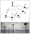 |
Figure 2. Measurement setup in free-field conditions with the rotor measurement platform (RMP) including the installed propeller on the right and five measurement microphones at different positions. |
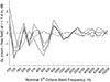 |
Figure 3. Half-free-field qualification measurement according to ISO 3745 [20], evaluated at 1.4 m distance between source and receiver. ΔL is the deviation from free-field conditions. |
The RMP is specifically designed to enable the mounting of a single rotor (propeller and motor) and precisely control its thrust and/or rotational speed. A schematic of the RMP is shown in Figure 4. The setup used in this study consists of the investigated propeller (see Sect. 3.1), driven by an iFlight XING2 2207 2755KV motor and controlled via a Hobbywing Skywalker 60A V2 electronic speed controller (ESC). The motor–propeller assembly is mounted on a 6-axis load cell (mini40 F/T Sensor, ATI Industrial Automation, Apex, NC 27539, USA), which is connected to a corresponding Net F/T sensor interface for force and torque measurements. Power is supplied by a laboratory power supply, while an Arduino microcontroller generates the pulse-width modulation (PWM) signal required to control the ESC.
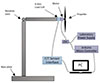 |
Figure 4. Scheme of the rotor measurement platform (not to scale) and installed devices used for the measurements. |
The base consists of a heavy metal ground plate to stabilize the construction, and the rotor is mounted on a metal pole with an adjustable revolute joint. For the presented work, it is set to 90° to operate the propeller horizontally. This, on the one hand, allows placing the microphones at different emission angles without space constraints and on the other hand, sends the downwash into the large rear section of the laboratory room to prevent air re-circulation and pressure build-up on the ground [22]. The overall lean design of the RMP minimizes reflections and the influence of the construction on the air flow.
We have previously shown that in forward flight, the propeller aerodynamics and therefore the sound characteristics can change significantly [23]. However, hover and slow cruise are common operating conditions, especially for surveillance tasks, aerial photography and scanning. In racing mode, i.e. for very fast flights with sharp turns, the noise emission is less relevant and is therefore not investigated further. The mass of drones with 5.1′′ propellers is usually in the range of 500–1500 g. In the case of a quadcopter, thrust forces between 1 and around 3.5 N per propeller are therefore relevant. For this study, we measured at thrust levels between 0.5 and 3.5 N in 0.5 N increments. For each propeller and thrust level, we simultaneously measured the electric power consumption, torque, rotational speed, and recorded the emitted sound for 30 s.
We captured the acoustic data with 1/2′′ free-field measurement microphones NTi M2230, feeding three two-channel Sound Devices 702T audio recorders. The calibration was conducted by using a Bruel & Kjær 4231 class 1 sound calibrator at 94 dB. We chose a 48 kHz sampling rate and bit depth of 24. The microphones were placed at propeller height, a distance of 1.4 m from the propeller center (see Fig. 2). To reduce wind-induced microphone noise from the downwash, we equipped the 80° microphone with a foam windshield.
3.3 In-flight measurements
As the sound from a flying drone compared to a single propeller differs due to installation effects and aerodynamic interactions (e.g., [11, 17]), we recorded a hovering quadcopter with propellers from each type. We chose the DJI Mini 3 Pro and let it hover at a constant distance of 1.25 m to the microphone, at a fixed vertical emission angle of φ = 60° (see Fig. 5). To mount the propellers, we used a 3D-printed adapter, as the measured propellers are not standard for this drone model. For each propeller type, we analyzed a 10 s recording in steady hover (constant thrust, no movement relative to microphone). The chosen drone type is particularly light, with a total mass of 250 g. We therefore expect a static thrust level for each propeller of 0.6 N to counterweight the drone’s weight. As the chosen drone type is small, we could fly it indoors without affecting the air-flow around it.
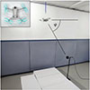 |
Figure 5. In-flight measurement situation, where we hovered a drone with each propeller type mounted indoors in free-field conditions (exemplary image of drone with toroidal propeller on the top left). We positioned it 1.25 m radial distance from the source at an emission angle of φ = 60°, facing towards the source. We attached a strap above the drone to keep its position exactly constant. |
3.4 Measurement data evaluation
We split the measurement data evaluation into two parts. The first part is the performance evaluation, and the second part is the acoustic evaluation. Performance data including thrust and torque were measured only for the static measurements on the RMP. For the in-flight measurements, we assumed that the torque is similar to the single propeller measurement and the thrust is determined by compensating the total weight of the drone. We compare all collected acoustic data at equal thrust levels.
3.4.1 Aerodynamic performance evaluation
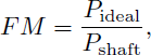
A common metric to quantify propeller efficiency in hover is the figure of merit (FM) [18], defined as
 (1)
(1)
where P ideal is the minimum theoretical power required to generate a given thrust in hover, and P shaft is the mechanical power delivered at the propeller shaft. The ideal power can be expressed as
 (2)
(2)
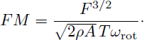
where F is the thrust, ρ the air density, and A the rotor disk area, defined as A = π D 2/4, with D being the propeller diameter [18]. The shaft power is obtained from the measured torque T and rotational speed ω rot as
 (3)
(3)
In this study, thrust F and torque T could be measured with the 6-axis load cell, while the rotational speed ω rot is determined acoustically from evaluating the BPF. Including equations (2) and (3) in equation (1), the expression of FM yields
 (4)
(4)
To enable comparison between propellers of different sizes and operating conditions, FM is commonly evaluated as a function of the thrust coefficient C T , defined as
 (5)
(5)
where C T is a dimensionless parameter expressing the thrust produced by a propeller normalized by air density, rotational speed, and propeller diameter [18].
3.4.2 Acoustic evaluation
As propellers exhibit a pronounced directivity, sound pressure levels are evaluated in directions relevant for ground-based observers. We chose a downward angle of 60° as a reference angle for most shown results. To enable comparability with other studies, all sound pressure levels are referenced to a distance of r 0 = 1 m from the propeller center, by correcting the geometrical spreading with 20log(r/r 0). To estimate the power spectral densities (PSD), we used Welch’s method with a Hamming window of 4096 samples, 50% overlap, and an FFT length of 8192. The measured background noise levels remained at least 15 dB below the propeller sound pressure levels across the evaluated frequency range, ensuring a sufficient signal-to-noise ratio for all presented spectra. We therefore do not show it within the plots.
4 Results
Figure 6a shows the FM as a function of thrust for each of the measured propellers. Throughout the whole thrust range, PhighPitch shows the lowest hover efficiency, whereas PlowPitch shows the highest. The toroidal propeller lies between the two reference propellers. Up to thrust levels of 2–2.5 N, FM increases for all propellers. This is typical for low thrust values, as drag is relatively large compared to the shaft power. At higher thrust, this fraction decreases and the propellers are more efficient up to a certain saturation point.
 |
Figure 6. Figure of merit for a single propeller at static thrust conditions as a function of thrust (left) and C T (right), for all tested propeller types (P). |
Figure 6b shows the FM as a function of the thrust coefficient C T . The linear growth of each FM over C T indicates that all propellers are operated in the low-thrust regime [18]. P lowPitch clearly exhibits the lowest C T due to its low pitch. If a propeller shows a lower C T at the same FM, it means the propeller reaches its best efficiency at a smaller blade loading, i.e., it is better optimized for low-thrust/hover conditions rather than for carrying high loads.
Figure 7 shows the A-weighted equivalent sound pressure level at a reference distance of 1 m to the propeller center (LAeq,1 m) as a function of thrust. It can be clearly seen that the toroidal propeller produces the highest sound pressure level overall. However, the sound pressure level appears to plateau at around 2 N thrust and increases only slowly beyond this point. The question arises if this trend persists beyond the thrust force level of 4 N. The results by Shima et al. [10] indicate a further sound emission level increase, and no plateau. PhighPitch exhibits the lowest SPL, being consistently around 5 dB lower than PlowPitch and up to 10 dB lower than the toroidal propeller.
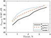 |
Figure 7. A-weighted equivalent sound pressure level at 1 m distance LAeq,1 m for a single propeller at static thrust conditions as a function of thrust at φ = 60°, for all tested propeller types (P). |
Figure 8 shows the A-weighted equivalent sound pressure level at a reference distance of 1 m to the propeller center at 2 N thrust (LAeq,1 m) for different emission angles, which indicates the directivity of each propeller. The toroidal and PlowPitch have a similar directivity pattern, with the former showing a higher SPL at all emission angles. They exhibit the lowest levels in the rotor plane, increasing towards the maximum at an emission angle of 60°. In comparison, PhighPitch propeller exhibits a less pronounced directivity pattern, with a maximum at 30°. At 60°, the toroidal propeller shows an increase in SPL of approximately 8 dB relative to PhighPitch.
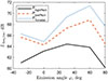 |
Figure 8. LAeq,1 m over emission angles (positive downward angles) at 2 N thrust and 1 m distance, measured for a single propeller (P) at static thrust conditions. |
Figure 9 presents the power spectral density (PSD) of all investigated propeller types at a fixed emission angle of 60° and a constant thrust of 2 N. Under these conditions, the toroidal propeller exhibits a comparatively high overall SPL (see Fig. 7). For all propeller types, the spectra are clearly dominated by tonal components, while the broadband contribution remains comparatively low. The pure tone at the rotational frequency frot is most pronounced for the toroidal propeller. The BPF tones of Ptoroidal and PhighPitch propellers show similar amplitudes and frequencies, whereas PlowPitch exhibits both a higher BPF amplitude and frequency, as its lower pitch requires higher rotational speed to generate the same thrust. Up to approximately 4 kHz, the amplitudes of the tonal components are of similar magnitude for all propellers. At higher frequencies, however, the toroidal propeller shows increased tonal levels, with a peak around 5 kHz reaching up to 5 dB higher than PlowPitch. Regarding broadband noise, PhighPitch exhibits the lowest levels, being up to 10 dB lower than the other propellers above 1 kHz. In contrast, the toroidal propeller shows elevated broadband noise levels above approximately 2 kHz, exceeding those of PlowPitch by up to 5 dB.
 |
Figure 9. Power spectral density (PSD) of the investigated propellers at φ = 60°, a thrust of 2 N, and a distance of 1 m under static operating conditions. |
Figure 10 shows the PSD of all measured propeller types from the hovering measurements at a fixed vertical emission angle of 60°, and the A-weighted equivalent sound pressure level LAeq. Based on the SPL shown in Figure 7 at this thrust level, PlowPitch was expected to exhibit similar SPL to the toroidal propeller, while PhighPitch was expected to exhibit lower sound pressure levels. The LAeq is equal for PlowPitch and PToroidal, and 2 dB lower for PhighPitch. This is confirmed by the measurement results in hover. In the mid frequency regime, the toroidal propeller exhibits also the highest tonal noise levels, and the highest broadband noise levels in the high-frequency regime. Compared to the single propeller PSD levels in Figure 9, the tonal components exhibit lower levels compared to the broadband components. This is expected, as during hover the propellers’ rotational speeds vary, leading to spectral smearing of tones – compared to the controlled RMP measurements. During hover, the toroidal propeller also shows the highest pure tone peaks.
 |
Figure 10. Power spectral density (PSD) of the propellers (P) installed on a hovering DJI Mini 3 Pro (mass: 250 g) at φ = 60° and a distance of 1.25 m. |
5 Discussion
5.1 Interpretation of results
The static test rig measurements have shown that the investigated toroidal propeller shows the highest SPL among all tested propellers. The hovering measurements confirm the static test rig measurements at low thrust, where we expected similar L Aeq for P Toroidal and P lowPitch and a lower L Aeq for P highPitch. These results qualitatively support the trends observed in the test rig measurements. While similar L Aeq values to those measured on the test rig are expected for heavier drones operating at higher thrust levels, larger differences are likely to occur, with the toroidal propeller exhibiting particularly high SPL. At the static measurements, we could show via C T analysis that the propellers are operated in the low-thrust regime. Even though P highPitch is the least efficient propeller in this thrust regime, it clearly shows the lowest SPL. Its figure of merit, however, shows that it is also somewhat less efficient than the other two. In this case, noise reduction comes at the cost of an efficiency decrease. This indicates that a propeller’s efficiency does not necessarily correlate with sound emission levels and may even show the opposite trend. However, P lowPitch demonstrates that conventional propellers can exhibit lower SPL while maintaining higher aerodynamic efficiency than toroidal propellers.
The directivity patterns shown in Figure 8, together with the calculated power spectral density in Figure 9, indicate that especially broadband and tonal components between 2 and 8 kHz are responsible for the noise level differences. According to [16], the increased broadband components of the toroidal propeller are either caused by high induced turbulences or by vortex noise, generated at the trailing edge or the tip of the blade. Due to the toroidal propeller’s lower efficiency combined with its higher noise emission level at typical thrust values, the higher broadband noise levels may indicate increased turbulent flow structures and unsteady aerodynamic interactions. According to [7], it produces even stronger and wider tip vortices than conventional propellers, which reduces the local blade loading and therefore aerodynamic efficiency. This increased turbulence may arise near the loop’s leading edge and subsequently affect the rear section of the loop. This finding is also supported by the investigations of Nakaniida et al. [24].
Compared to the findings of Shima et al. [10], the investigated commercial two-loop toroidal propeller did not exhibit reduced tonal or overall sound pressure levels relative to the conventional reference propellers. However, we found important similarities in their spectral characteristics. While Shima et al. reported strong reductions of tonal blade-passing-frequency components for an optimized three-loop toroidal propeller, they also observed increased broadband noise levels above approximately 4 kHz, which they attributed to turbulence and flow separation near the looped tip geometry. This interpretation is qualitatively consistent with the increased high-frequency broadband noise observed in the present study. In addition, Shima et al. reported an approximately 10% lower figure of merit compared to a conventional two-bladed baseline propeller, which is also consistent with the reduced efficiency observed here. The differing acoustic behavior between both studies is likely related to substantial differences in blade count, loop arrangement, and the use of a Gurney flap for aeroacoustic optimization. In particular, the tonal noise reduction reported for the three-loop propeller may partially result from distributing the aerodynamic loading over a larger effective blade area, thereby reducing loading fluctuations per blade passage, rather than from the toroidal geometry alone. Although optimized toroidal geometries may achieve lower SPL than the investigated commercial design, the optimized three-loop propeller investigated by Shima et al. reduced the OASPL by only approximately 2.1 dB relative to their conventional baseline. Applying a comparable reduction to the investigated toroidal propeller in the present study would still result in SPL values comparable to or higher than those of the conventional reference propellers for most investigated thrust conditions.
The investigated toroidal propeller may effectively be regarded as a four-bladed configuration with uneven blade spacing and closed-loop blade tips, whereas the baseline propellers are conventional two-bladed designs. Previous studies have shown that increasing blade count can reduce emitted noise levels, particularly broadband noise components [25]. Consequently, considering blade count alone, the investigated toroidal propeller could be expected to exhibit lower noise emissions than the two-bladed reference propellers. However, the toroidal propeller additionally differs in its closed-loop geometry, asymmetric blade distribution, and altered aerodynamic loading characteristics, which may introduce additional unsteady aerodynamic interactions that counteract potential acoustic benefits associated with increased blade count.
5.2 Limitations and future work
The present study is limited to the investigation of three specific propeller geometries. Future studies including a broader range of toroidal and conventional propeller designs would improve the generalization of the observed aerodynamic, acoustic, and psychoacoustic trends.
The present comparison does not constitute a fully isolated concept-to-concept comparison, as the investigated toroidal propeller rather represents a four-bladed configuration, whereas the reference propellers are conventional two-bladed designs. Future investigations should therefore compare toroidal and conventional propellers with systematically matched blade count and aerodynamic loading to better isolate the acoustic effects of the toroidal geometry itself.
Beyond its focus on a single, commercially available toroidal propeller type, the study is further limited to operating conditions corresponding to hover. However, prior work suggests that additional effects may arise under different operating regimes. A study by Meister et al. [23] has shown that, under cruise conditions, blade–vortex interactions can increase the emitted sound by several decibels. In addition, the computational study by Li et al. [7] revealed that for toroidal propellers, “a stronger and wider tip vortex is shed from the connection region in comparison to conventional rotors.” Based on these findings, toroidal propellers may exhibit even higher SPL under forward-flight conditions.
6 Conclusion
In this study, we compared a commercially available 5-inch toroidal propeller with two conventional two-bladed propellers of the same diameter (baseline) regarding sound emission and efficiency at hover conditions. Measurements were conducted both on a static test rig and in flight using a hovering quadcopter.
The results show that the investigated toroidal propeller does not provide an acoustic or aerodynamic advantage over the conventional designs. Instead, it exhibits similar or up to 10 dB higher SPL, depending on the thrust level, and shows the highest SPL at all observer-relevant emission angles. Spectral analyses further reveal that the increased A-weighted noise levels are particularly pronounced at frequencies above 3–4 kHz. In terms of efficiency, the toroidal propeller shows no benefit compared to the conventional propellers and lies between the two baseline designs.
The high-pitch baseline propeller exhibited the lowest noise levels, although it was slightly less efficient, whereas the low-pitch baseline achieved the highest efficiency while showing lower SPL than the toroidal design. Previous studies on toroidal propellers have reported mixed results, ranging from substantial noise reductions to slight noise increases. However, many of these investigations were limited in terms of frequency range, modeled noise components, or experimental reproducibility. The present results, together with a review of recent studies, indicate that currently available off-the-shelf toroidal propellers do not outperform well-designed conventional blades under hover conditions. It should be noted that this study considered only a single two-loop toroidal geometry at hover conditions. Future work should therefore include more toroidal and baseline propeller geometries to enhance generalization and extend the investigation to cruise conditions, where looped designs may interact differently with tip vortices and the surrounding flow field.
Funding
This work was partially funded by the Federal Office of Civil Aviation (FOCA) under the Spezialfinanzierung Luftverkehr (SFLV), grant no. 2024-033.
Conflicts of interest
The authors declare no conflict of interest.
Data availability statement
All measurement data are available on request from the authors.
Author contribution statement
JM: Methodology, Measurements, Writing (Original Draft), Visualization, Resources, Funding Acquisition. TVR: Writing (Editing and Review), Supervision. RP: Writing (Editing and Review), Supervision, Funding Acquisition, Conceptualization.
References
- B. Schäffer, R. Pieren, K. Heutschi, J.M. Wunderli, S. Becker: Drone noise emission characteristics and noise effects on humans–A systematic review. International Journal of Environmental Research and Public Health 18, 11 (2021) 5940. [CrossRef] [PubMed] [Google Scholar]
- European Commission: Commission Delegated Regulation (EU) 2019/945 of 12 March 2019 on unmanned aircraft systems and on third-country operators of unmanned aircraft systems. Official Journal of the European Union L 152 (2019). https://eur-lex.europa.eu/eli/reg_del/2019/945/oj. [Google Scholar]
- European Union Aviation Safety Agency (EASA): Guidelines on Noise Measurement of Unmanned Aircraft Systems Lighter than 600 kg Operating in the Specific Category (Low and Medium Risk), 2023. https://www.easa.europa.eu/en/downloads/137139/en. [Google Scholar]
- ISO 5305:2024 (E): Noise measurements for UAS (unmanned aircraft systems), 2024. https://www.iso.org/standard/81111.html. [Google Scholar]
- T. Sebastian, C. Strem: Toroidal Propeller. Massachusetts Institute of Technology (MIT), US10836466B2, 2017. [Google Scholar]
- J. Lee, J. Choi: Parametric study of toroidal propellers for development of low-noise design technology using CFD. Journal of Mechanical Science and Technology 39 (2025) 3621–3628. [Google Scholar]
- P.Y. Li, C.F. Liu, Y. Liu, Y.N. Yang: Multi-objective design and evaluation of a toroidal rotor for quadcopters. Physics of Fluids 36, 12 (2024). https://doi.org/10.1063/5.0243175 [Google Scholar]
- W. Wei, Y. Ma, S. Wei, D. Wang, M. Guo, Q. Yan: Analysis and evaluation of aerodynamic noise characteristics of toroidal propeller. Drones 8, 12 (2024) 753. [Google Scholar]
- J. du Plessis, A. Bouferrouk: Aerodynamic and aeroacoustic analysis of looped propeller blades, in: 30th AIAA/CEAS Aeroacoustics Conference. American Institute of Aeronautics and Astronautics, 2024. https://doi.org/10.2514/6.2024-3156. [Google Scholar]
- E. Shima, H. Kaneko, J.W. Sun, H. Liu, K. Yonezawa: Aeroacoustics, psychoacoustics, and aerodynamic characteristics of innovative looped propellers using catenary curves, in: 30th AIAA/CEAS Aeroacoustics Conference. American Institute of Aeronautics and Astronautics, 2024. https://doi.org/10.2514/6.2024-3111. [Google Scholar]
- M. Roger, S. Moreau: Tonal-noise assessment of quadrotor-type UAV using source-mode expansions. Acoustics 2 (2020) 674–690. [Google Scholar]
- F. Farassat: Derivation of Formulations 1 and 1A of Farassat. Langley Research Center, 2007. https://ntrs.nasa.gov/citations/20070010579. [Google Scholar]
- T.F. Brooks, C.L. Burley: Rotor broadband noise prediction with comparison to model data, in: 7th AIAA/CEAS Aeroacoustics Conference, 2001. https://doi.org/10.2514/6.2001-2210. [Google Scholar]
- I. Proudman: The generation of noise by isotropic turbulence. Proceedings of the Royal Society of London. A. Mathematical and Physical Sciences 214 (1952) 119–132. [Google Scholar]
- W. Johnson: Rotorcraft Aeromechanics. Cambridge University Press, 2013, pp. 493–544. [Google Scholar]
- J.E. Marte, D.W. Kurtz: A Review of Aerodynamic Noise from Propellers, Rotors, and Lift Fans. California Institute of Technology, Pasadena, CA, 1970. [Google Scholar]
- N.S. Zawodny, N.A. Pettingill: Acoustic wind tunnel measurements of a quadcopter in hover and forward flight conditions, in: INTER-NOISE 2018 – 47th International Congress and Exposition on Noise Control Engineering: impact of Noise Control Engineering, 2018. [Google Scholar]
- J.G. Leishman: Principles of Helicopter Aerodynamics. University of Maryland, Cambridge University Press, 2000. [Google Scholar]
- K. Heutschi, B. Ott, T. Nussbaumer, P. Wellig: Synthesis of real world drone signals based on lab recordings. Acta Acustica 4, 6 (2020) 24. [CrossRef] [EDP Sciences] [Google Scholar]
- ISO 3745:2012 (E): Acoustics – Determination of sound power levels and sound energy levels of noise sources using sound pressure – Precision methods for anechoic rooms and hemi-anechoic rooms, 2012. https://www.iso.org/standard/45362.html. [Google Scholar]
- ISO 10534-2:2023: Acoustics – Determination of acoustic properties in impedance tubes, Part 2: two-microphone technique for normal sound absorption coefficient and normal surface impedance, 2023. https://www.iso.org/standard/81294.html. [Google Scholar]
- D. Weitsman, J.H. Stephenson, N.S. Zawodny: Effects of flow recirculation on acoustic and dynamic measurements of rotary-wing systems operating in closed anechoic chambers. The Journal of the Acoustical Society of America 148, 3 (2020) 1325–1336. [CrossRef] [PubMed] [Google Scholar]
- J. Meister, J. Jaeggi, T. Van Renterghem, R. Pieren: Measured differences in the sound emission of multi-rotor unmanned aerial systems during hover and cruise. The Journal of the Acoustical Society of America 159, 3 (2026) 2398–2415. [Google Scholar]
- Y. Nakaniida, M. Sato, E. Shima: Numerical study on aerodynamic characteristics of loop propeller toward quiet eVTOL, in: AIAA Aviation Forum. American Institute of Aeronautics and Astronautics, 2024. https://doi.org/10.2514/6.2024-4521. [Google Scholar]
- K. Baskaran, N.S. Jamaluddin, A. Celik, D. Rezgui, M. Azarpeyvand: Effects of number of blades on propeller noise. Journal of Sound and Vibration 572 (2024) 118176. [Google Scholar]
Small tab mounted perpendicular to the trailing edge of a propeller blade to increase lift by modifying the airflow and pressure distribution behind the blade.
Cite this article as: Meister J. Van Renterghem T. & Pieren R. 2026. Acoustic and aerodynamic performance evaluation of a commercial toroidal propeller compared to conventional propellers. Acta Acustica, 10, 57. https://doi.org/10.1051/aacus/2026057.
All Tables
Overview of methodologies, noise modeling/measuring approaches, and frequency ranges in studies on toroidal propeller noise. Abbreviations: FW–H: Ffowcs Williams–Hawkings Analogy, BL: Boundary Layer Source Model, BEM: Boundary-Element Method, BB: Broadband.
Extension of Table 1. Reported noise reduction potential, reproducibility (qualitative author assessment), and aerodynamic performance assessment of toroidal propellers. Abbreviations: OASPL: Overall A-weighted sound pressure level, BPF: Blade passing frequency, RANS: Reynolds-Averaged Navier–Stokes method, CFD: Computational Fluid Dynamics.
All Figures
|
Figure 1. Measured propeller types. Left: Toroidal propeller (P Toroidal). Center: Low-pitch propeller (P lowPitch). Right: High-pitch propeller (P highPitch). |
| In the text | |
|
Figure 2. Measurement setup in free-field conditions with the rotor measurement platform (RMP) including the installed propeller on the right and five measurement microphones at different positions. |
| In the text | |
|
Figure 3. Half-free-field qualification measurement according to ISO 3745 [20], evaluated at 1.4 m distance between source and receiver. ΔL is the deviation from free-field conditions. |
| In the text | |
|
Figure 4. Scheme of the rotor measurement platform (not to scale) and installed devices used for the measurements. |
| In the text | |
|
Figure 5. In-flight measurement situation, where we hovered a drone with each propeller type mounted indoors in free-field conditions (exemplary image of drone with toroidal propeller on the top left). We positioned it 1.25 m radial distance from the source at an emission angle of φ = 60°, facing towards the source. We attached a strap above the drone to keep its position exactly constant. |
| In the text | |
|
Figure 6. Figure of merit for a single propeller at static thrust conditions as a function of thrust (left) and C T (right), for all tested propeller types (P). |
| In the text | |
|
Figure 7. A-weighted equivalent sound pressure level at 1 m distance LAeq,1 m for a single propeller at static thrust conditions as a function of thrust at φ = 60°, for all tested propeller types (P). |
| In the text | |
|
Figure 8. LAeq,1 m over emission angles (positive downward angles) at 2 N thrust and 1 m distance, measured for a single propeller (P) at static thrust conditions. |
| In the text | |
|
Figure 9. Power spectral density (PSD) of the investigated propellers at φ = 60°, a thrust of 2 N, and a distance of 1 m under static operating conditions. |
| In the text | |
|
Figure 10. Power spectral density (PSD) of the propellers (P) installed on a hovering DJI Mini 3 Pro (mass: 250 g) at φ = 60° and a distance of 1.25 m. |
| In the text | |
Current usage metrics show cumulative count of Article Views (full-text article views including HTML views, PDF and ePub downloads, according to the available data) and Abstracts Views on Vision4Press platform.
Data correspond to usage on the plateform after 2015. The current usage metrics is available 48-96 hours after online publication and is updated daily on week days.
Initial download of the metrics may take a while.